Calculation error ?

giovanniluigi

New member
I suspect there may be a systematic error in Evolution (and possibly even earlier versions') software radio calculations. Specifically, when an input has scaling applied, then the output seems to have an unwanted dependence on a non-zero expo value.

For example, using a stock Extra 300L in high rates, consider a rudder “Output Channel 4”, with Input being “Input Channel 4 (Left Stick, X Axis)” ranging from -100% to +100%. Set the input scaling Percent (%) = 80 and the Output should range +/-80%. It does so, if “Expo During High Rates (%)” is set to 0, but when this expo is set for anything different than 0%, e.g. 40%, then the output ranges less than +/-80% (the specific amount being dependent on the expo percentage), in this case +/- 63.9%.

In my experience with real radios, such as Futaba, PowerBox, etc., any amount of Expo results in the travel endpoints being unchanged from those with a 0% expo (i.e. the linear curve). In other words, the expo % is not equivalent to "scaling", but to "shaping" the output according with an exponential curve, where the expo % only relates to how much the curve deviates (normally lower) from linear around the center, to desensitize the input from small movements of the stick, leaving the endpoints unchanged. The rate value (e.g. high rate, low rates, etc.) is the one that can affect the travel endpoints, not the expo value.

Am I missing something?
 
I just loaded one of my planes and set the low-rate to 80%, the output was +/-80. I set the low-rate Expo to 50% and the output was +/-80. It seems to work as expected for me. The Exponential When was set to Always. This was a InterLink-X controller if it matters.
 
I suspect there may be a systematic error in Evolution (and possibly even earlier versions') software radio calculations. Specifically, when an input has scaling applied, then the output seems to have an unwanted dependence on a non-zero expo value.

For example, using a stock Extra 300L in high rates, consider a rudder “Output Channel 4”, with Input being “Input Channel 4 (Left Stick, X Axis)” ranging from -100% to +100%. Set the input scaling Percent (%) = 80 and the Output should range +/-80%. It does so, if “Expo During High Rates (%)” is set to 0, but when this expo is set for anything different than 0%, e.g. 40%, then the output ranges less than +/-80% (the specific amount being dependent on the expo percentage), in this case +/- 63.9%.

In my experience with real radios, such as Futaba, PowerBox, etc., any amount of Expo results in the travel endpoints being unchanged from those with a 0% expo (i.e. the linear curve). In other words, the expo % is not equivalent to "scaling", but to "shaping" the output according with an exponential curve, where the expo % only relates to how much the curve deviates (normally lower) from linear around the center, to desensitize the input from small movements of the stick, leaving the endpoints unchanged. The rate value (e.g. high rate, low rates, etc.) is the one that can affect the travel endpoints, not the expo value.

Am I missing something?

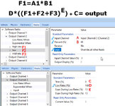
Scaling the input is not a true low rate. Input scale is like putting physical limiter on the gimbal. Not truely adjusting the output as a "lowrate". which on real radios is applied after the EXPO. the RF expo and lowrates works just like real radios, apply the expo to the inputs then apply the lowrate percent to the expo curve (read the formula in the image)

so realflight can not tell the difference between scaling the input to 50% and pulling all the way back and only pulling 50% back on the stick. low rate are handled differently and applied after the expo. But the workaround for triple rates (discussed in the previous tread) applies the "rates" before the expo in the formula and thus is end up having different endpoint after the expo.

the basic flow for inputs
  1. read the sticks
  2. multiple sticks by input%
  3. sum enabled inputs
  4. apply the expo to the summed inputs; if Exponential When currently is true
  5. multiple by low rates (%); if low rates When currently is true
  6. add trim(%)
  7. send output to receiver on vehicle
if you want to get crunchy with the math and the formulas you can keep reading.

the expo has it own formula that ranges in outputs between [-0.5,2.0] with inputs [-100%,100%] and the input 0 outputting 1

with how the main out formula works and the output usually being between -1 and 1 not including inputs C and D. Appling an positive expo will make the number closer to zero. Then when we scale make B (input scale) smaller and redue the max output from [-1,1] by to [-B,B].

example set B to 50 and E to max for max expo. it scales the output of F to [-0.5,0.5] then we apply the expo and we are now at [-0.25,0.25]

input formula.jpg
 
Scaling the input is not a true low rate. Input scale is like putting physical limiter on the gimbal. Not truely adjusting the output as a "lowrate". which on real radios is applied after the EXPO. the RF expo and lowrates works just like real radios, apply the expo to the inputs then apply the lowrate percent to the expo curve (read the formula in the image)

so realflight can not tell the difference between scaling the input to 50% and pulling all the way back and only pulling 50% back on the stick. low rate are handled differently and applied after the expo. But the workaround for triple rates (discussed in the previous tread) applies the "rates" before the expo in the formula and thus is end up having different endpoint after the expo.

the basic flow for inputs
  1. read the sticks
  2. multiple sticks by input%
  3. sum enabled inputs
  4. apply the expo to the summed inputs; if Exponential When currently is true
  5. multiple by low rates (%); if low rates When currently is true
  6. add trim(%)
  7. send output to receiver on vehicle
if you want to get crunchy with the math and the formulas you can keep reading.

the expo has it own formula that ranges in outputs between [-0.5,2.0] with inputs [-100%,100%] and the input 0 outputting 1

with how the main out formula works and the output usually being between -1 and 1 not including inputs C and D. Appling an positive expo will make the number closer to zero. Then when we scale make B (input scale) smaller and redue the max output from [-1,1] by to [-B,B].

example set B to 50 and E to max for max expo. it scales the output of F to [-0.5,0.5] then we apply the expo and we are now at [-0.25,0.25]

View attachment 137823

I really would like to understand what you are saying, but I am failing at it, and not because I cannot read a formula 😊

My example above has nothing to do with a “workaround for triple rates” (that was another discussion) or even dual rates. I just described what happens in a very simple situation of only high rates and only one input. Using your words, about the basic calculation flow (in parenthesis are the endpoint values from my example)

“read the sticks (-100% to +100%)

multiply sticks by input% (for B = 80, -80% to +80%)

sum enabled inputs (only one input here)

apply the expo to the summed inputs, if Exponential When currently is true (for any expo value, the endpoints should still be -80% and +80%. Expo should only affect the curve between the endpoints)

multiply by low rates (%); if Low Rates When currently is true (no Low Rates involved in this example)

add trim(%) (no trim in this example)

send output to receiver on vehicle”

What I am saying is the RF calculation seems to affect the endpoints (not just the curve in between them), for any values of expo different than zero, and that is not what real radios do.

Also, please clarify the meaning of “the expo has its own formula that ranges in outputs between [-0.5,2.0] with inputs [-100%,100%] and the input 0 outputting 1”. What is the input variable in this formula? How does the expo change the output curve, with this formula?
 
I really would like to understand what you are saying, but I am failing at it, and not because I cannot read a formula 😊

My example above has nothing to do with a “workaround for triple rates” (that was another discussion) or even dual rates. I just described what happens in a very simple situation of only high rates and only one input. Using your words, about the basic calculation flow (in parenthesis are the endpoint values from my example)

I probably should have removed the triple rates part. Apologies it was late and I was tired.

What I am saying is the RF calculation seems to affect the endpoints (not just the curve in between them), for any values of expo different than zero, and that is not what real radios do.

also the input percent is closer to a restictor plate on the gimbal without recalibrating than a output scale available on modern radios. If you only need 80% of travel at the control surface. Changing the linkages in Real life and is the best way and in Real flight that is "similfied" to a degree output. limiting servo travel to 80% is "hard" on servos as it limits it mechanical advantage on the control surface.

read the sticks (-100% to +100%)
multiply sticks by input% (for B = 80, -80% to +80%)
sum enabled inputs (only one input here)
all good
apply the expo to the summed inputs, if Exponential When currently is true (for any expo value, the endpoints should still be -80% and +80%. Expo should only affect the curve between the endpoints)
Because RF applies the expo to the sum of input. not to the individual sticks. Scaling before this point can have adverse simulation.

multiply by low rates (%); if Low Rates When currently is true (no Low Rates involved in this example)
add trim(%) (no trim in this example)
send output to receiver on vehicle”

Also, please clarify the meaning of “the expo has its own formula that ranges in outputs between [-0.5,2.0] with inputs [-100%,100%] and the input 0 outputting 1”. What is the input variable in this formula? How does the expo change the output curve, with this formula?

Also I mis-typed the output range it is not [-0.5, 2.0] it is [0.5, 2.0]. sorry if that was the source of the confusion.

in the graph below
the horizontal axis is the Sum of inputs
the vertical axis is the output of the expo
the blue curve is max negative expo
the orange curve is max positive expo
the green is zero expo (input = output)
2024-02-09 18_26_28-graph y = x_abs(x)^(-0.5), y = x_abs(x)^(1), and y=x from [-1,1] - Wolfram...png
 
Last edited:
I probably should have removed the triple rates part. Apologies it was late and I was tired.


also the input percent is closer to a restictor plate on the gimbal without recalibrating than a output scale available on modern radios. If you only need 80% of travel at the control surface. Changing the linkages in Real life and is the best way and in Real flight that is "similfied" to a degree output. limiting servo travel to 80% is "hard" on servos as it limits it mechanical advantage on the control surface.


all good

Because RF applies the expo to the sum of input. not to the individual sticks. Scaling before this point can have adverse simulation.


Also I mis-typed the output range it is not [-0.5, 2.0] it is [0.5, 2.0]. sorry if that was the source of the confusion.

in the graph below
the horizontal axis is the Sum of inputs
the vertical axis is the output of the expo
the blue curve is max negative expo
the orange curve is max positive expo (input = output)
the green is zero expo (input = output)
View attachment 137836

Thanks for the clarifications!

I agree that in RealFlight scaling the input seems to have adverse (I’d say unexpected) effects for the simulation. I first noticed such fact as I was analyzing a model proposed by RCFS (Extra 330SC (InterLink) by RCFS_AV).

As for the Expo graph, what you show is exactly what I would expect, as Output vs Input curve. By the way, I think you have a typo, as the orange curve (Expo = 100%) is not input=output. That is only for the green curve (Expo = 0%). All curves show the output endpoints being unaffected by Expo.

But clearly the graph does not explain to me what you mean by the output range being +0.5 to 2.0. Range of what? Is the variable the Expo percentage?
I just want to make sure my above reference to RCFS (First US RC Flight School) is not construed as criticism of them. RCFS properly used input scaling to implement the various mixes found in a typical IMAC competition airplane, such as rudder-to-aileron, rudder-to-elevator, low throttle-to-down elevator, etc.
The plane flies well in the simulation. However, the problem is that, if one tries to adjust the amount of expo to suit his own flying style, there will also be an unexpected/unwanted change in the maximum deflection of the control surface. That is what prompted my investigation and I now realize the issue is due to the internal calculations for the software radio in RealFlight.
 
Thanks for the clarifications!

I agree that in RealFlight scaling the input seems to have adverse (I’d say unexpected) effects for the simulation. I first noticed such fact as I was analyzing a model proposed by RCFS (Extra 330SC (InterLink) by RCFS_AV).

As for the Expo graph, what you show is exactly what I would expect, as Output vs Input curve. By the way, I think you have a typo, as the orange curve (Expo = 100%) is not input=output. That is only for the green curve (Expo = 0%). All curves show the output endpoints being unaffected by Expo.

But clearly the graph does not explain to me what you mean by the output range being +0.5 to 2.0. Range of what? Is the variable the Expo percentage?

yes it was a typo. I was trying to figure out how to write input raise to the exponenial in a simple manner with out superscripts. and again it was too close to my bed time and I was distracted by someone wanting help on a rf project.

the blue curve is max negative expo (input^0.5 = output) input to the 0.5 power
the orange curve is max positive expo (input^2.0 = output) input to the 2.0 power
the green is zero expo (input = output) input to the 1.0 power

the conversion for the expo% [-100%,100%] to the actual exponent applied to input [0.5,2.0]


if expo%>=0 return 1+expo% ;
elseif expo%<0 return 1/(1-expo%)); since expo is negative it return a vaule less than one

Thanks! That finally explains to me well how the expo calculation is done (y=x to the power of e, where e is given by the code snippet above).

As a last comment, I believe the entire basic calculation flow would be correct and resolve the issue I originally noticed, if modified as follows:

- Read the stick value;

- Multiply stick value by scaling factor (input%) and by the value obtained from above expo curves, depending on the selected Rate;

- Add all other enabled inputs, each multiplied by its individual scaling factor;

- Multiply the Sum by Low Rates (%), if "Low Rates When" is true;

- Add Trim(%);

- Send Output to receiver on vehicle
 
Back
Top