Complete newbie needs 3DSmax 2010 help

zbrubaker

New member
I have a model of a plane I want to create for RealFlight 3.5. I created the model in AutoCAD and exported to the 3DS format and opened in 3DSmax 2010. I have figured out how to link the entities together in the proper hierarchy, but for the life of me I cannot figure out how to hinge things like the ailerons, elevators, landing gear, etc...

I am completely new to 3DS but have been using AutoCAD for over 20 years. It is a completely different way of thinking. Any help would be greatly appreciated!

TIA

Zeke
 
There is a great tutorial on how to build an aircraft. I don't remember where it is, but if search for it, you should find it
 
Have you been to the KEmax tutorial section?
http://www.knifeedge.com/KEmax/tutorials.php

Also, noticed you are posting in the G3.5 forum.
If you intend to use your model in G3.5 you must use Max9.
Sorry to say all the .kex file by kemax exporters after Max9 only work with G4 and above. :(

Workaround would be to export as .3ds file and then use the dos based 3ds2kex exporter to create a usable file.

Good Luck...
 
phrank said:
Have you been to the KEmax tutorial section?
http://www.knifeedge.com/KEmax/tutorials.php

Also, noticed you are posting in the G3.5 forum.
If you intend to use your model in G3.5 you must use Max9.
Sorry to say all the .kex file by kemax exporters after Max9 only work with G4 and above. :(

Workaround would be to export as .3ds file and then use the dos based 3ds2kex exporter to create a usable file.

Good Luck...
That was my intention to export to 3DS and use 3ds2kex utility. I have gone through the tutorials, but they are basic in they only say to create the hinge/pivot point, not how to actually do it.
 
There is nothing terribly complex about it.
Set up you pivot axis for ailerons, elevator, rudder etc...
Follow the naming conventions and hierarchy.

I believe the tutorials are quite clear.
The included sample aircraft should also be a useful guide.
 
phrank said:
There is nothing terribly complex about it.
Set up you pivot axis for ailerons, elevator, rudder etc...
Follow the naming conventions and hierarchy.

I believe the tutorials are quite clear.
The included sample aircraft should also be a useful guide.
Well, for someone with ZERO experience with 3DS Max, I don't know the tools and I don't know the 'lingo', so it's not quite that clear or simple. It's easy to say "set up a pivot axis" when you know HOW to do it, I don't. Working in 3DS Max is an entirely different mindset/concept for me. It would be simple if I could just pick an object or points to use as a pivot axis, but it seems I have to create and set constraints and do other things that I just don't grasp the concept of yet. If I could see/read exactly how it's done, I could understand the concept. It's just not intuitive to me (yet).
 
My mistake, I mistook the 20yrs experience using a 3D package as a leg up on the rest of us. :eek:
The terminology and tools vary very little amongst 3D packages, but the general concept is the same.

OK let's try this another way:
Allow me to introduce you to the vast resources of the Internet and the SEARCH function, where anything you wanted to learn just about everything is just a few keystrokes away:
Let's take the keyword "3ds max pivot" to YouTube search for example:
That keyword takes us to several search results, including this (top of the list):
http://www.youtube.com/watch?v=DXCVQLLe4ks

Hope that helps you on your way.

Good Luck...
 
phrank said:
My mistake, I mistook the 20yrs experience using a 3D package as a leg up on the rest of us. :eek:
The terminology and tools vary very little amongst 3D packages, but the general concept is the same.

OK let's try this another way:
Allow me to introduce you to the vast resources of the Internet and the SEARCH function, where anything you wanted to learn just about everything is just a few keystrokes away:
Let's take the keyword "3ds max pivot" to YouTube search for example:
That keyword takes us to several search results, including this (top of the list):
http://www.youtube.com/watch?v=DXCVQLLe4ks

Hope that helps you on your way.

Good Luck...
Please don't be condescending, it's really uncalled for and totally unnecessary. I believe I clearly stated I have 20 years of AutoCAD experience...AutoCAD is a far cry from a 3D surface modeling/animation program like 3DS Max (which I have no experience with ANY 3D surface modeling/animation program). I also clearly indicated I'm using 3DS Max 2010. The tool interfaces have been completely revamped from the version 9 in the YouTube video you linked above, so what is shown is meaningless since I can't duplicate what is being shown.

I am well aware of how to use the internet and search functions. You assumed that I have not already spent a fair bit of time searching for the information I am asking for. And you are wrong. All of the information I have found is a bit confusing as it is disjointed at best. That is why I came to this forum and asked here since it is a forum specific to what I am trying to learn and accomplish.

So I would appreciate if you are unwilling to help someone that is completely new to 3DS Max and 3D surface modeling/animation in general, then refrain from posting.

As stated, I have already created my 3D model in Autocad as a solid model and exported it to the 3DS format. I have imported the 3DS surface model into 3DS Max 2010. I have linked the surfaces into the hierarchy (aileron linked to wing, wing linked to fuselage, etc...).

What I need to know are the proper steps involved so that the aileron is hinged to the wing, or the elevator is hinged to the horizontal stabilizer or the retractable landing gear can pivot into the fuselage, etc...
 
Last edited:
As you wish sir.... :confused:

zbrubaker said:
So I would appreciate if you are unwilling to help someone that is completely new to 3DS Max and 3D surface modeling/animation in general, then refrain from posting.
 
Hummmm what to say.......

Hey Zbrubaker

Welcome to the forums. As a person that started Many Many Year Ago in a Galaxy Far Far away with AutoCad ( 12 5 ¼ Floppies ) and then moving on to (Small business Design ) Design Cad 3d, I know the feeling. The fist time you look at a surface molder it is mind blowing. I'm slowing going through the lessens plans for Catia R7 for RC parts modeling.

Let me ask you a few questions. What program will you be using for making the UV Map ( skin or Texture map ) I never did any of that in Auto Cad. In the business world that would be your graphics designer that do that after the molder finished the 3d work and passed it off. The reason I'm asking is you might be able to finish the Real Flight Model with out using 3d Max 10. As long as you map it with a third party utility ( or Auto Cad ) and use the program Deep Exploration. You can assign texture properties ( flat or shinny ect ), set the Hierarchy linking, and set the Pivots with it. Then run 3ds2kex.exe ( command line program )

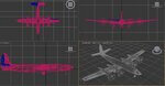
Ok Pivots points. Don't get scared by this. It is not a animated sequence of multiple frame positions or a Point A and point B Move command as in old school 3d movements. When you exported your model out of AC in to the 3ds format It came in with all the sperate parts as a collection of parts with a SINGLE center of mass. I cant remember what AC called it but it is your XYZ reference point, dead center the mass. This is really what the pivot points are, the Dead center of the Mass XYZ reference point. But of course it would look silly with the tires, flaps, and other moving parts rotating around the center of the aircraft. You'll need to pick the parts the need to move on the aircraft and set in there properties it own center of mass XYZ reference point, and of course move it to where you think the hinge point would be on the part you molded. That is a pivots point in a nut shell. RF will do the moving after you get it in to the RF editor

Ok again so I did not tell you how to do it in 3d Max 10. I know. We get asked these type of questions once a week and they get answer or get pointed to location where the information can be found. THIS IS NOT A 3D MAX FORUM, and it not the place to learn how to use the program you bought. This forum can tell you if the file you made will work, what that file needs to work, how to run the 3ds2kex program to get a KEX Real Flight file, and how to adjust you final RF creation as long as you willing to do some reading through this forum. I believe you said "" I am well aware of how to use the Internet and search functions."" Phrank was talking about the SEARCH FUNCTION of this forum. TOP blue bar , the word search..??


Ok again and again. With that all said lets see a picture of the model, Not trying to drag you through the dirt of laugh at your work, but first of all we need to see if it is even able to work in RF because of the number of polyies ( faces ). Is it over the limit. What the Limit you ask? Search this forum.

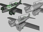
Here is an example of what we see here a lot. I Made this plane, I got this plane, I down loaded this plane..... Ect Ect Ect you can all ready see where I going with this. Big difference is he asked a few question and then went back and changed the stuff that was needed. It took some time but he figured it out
.
Http://knifeedge.com/forums/showthread.php?t=22811


And his all most final work. Notice the few month in-between post.

https://forums.realflight.com/showthread.php?t=23958
 
Last edited:
Thanks for the response Terry. I too started back with the old school AutoCAD (v 9 I believe) and trying to use a surface modeling program is like learning a foreign language. Getting my mind around the concepts of 3D modeling is the tough part. Even though there are many CAD programs that I have never used, I know I could be up and running with most of them is a short period of time because I understand the concepts of CAD. The same will hold true for 3D surface modeling (eventually). :rolleyes:

As to the UV mapping, I don't know at this point, but I am open to suggestions. I'm trying to tackle each step one at a time. It seemed the logical order to get the model completed first and then move on to the texture mapping.

Thanks for the info on the pivot point, that really clears up the concept for me. Now to learn how that actually translates into 3DS which should be much easier now knowing what I need to do. I had read somewhere about having the airframe CG set at the origin (0,0,0) prior to exporting to the 3DS format, so I moved the model so that it's CG/CoM is at 0,0,0.

I've uploaded a pic of the model. I think I should be fine as I believe I am well under the 80,000? facet limit. **edit** make that 20,000!
 

Attachments

  • 3DS Screen Shot.JPG
    3DS Screen Shot.JPG
    88.7 KB · Views: 33
Last edited:
Thanks for your help Terry, knowing what the pivot point is helped me to get it worked out in 3DS Max. I still have a few more to do as it's a bit quirky (for now at least) getting the pivot point aligned with the hinge line I want. I checked the model and I have 17,600 facets.
 
1 question

Is the face number with, OR without a Collision Mesh.

If you already have a COLL, I'd max out the polies and add some serious detail to it.
 
next question

I guess the next question coming is. What's a Collision Mesh :)


I said this in a few thread so far but I'll be bizzzy this weekend and next week roofing. Will get back to you if you need more help.
 
Junkboy999 said:
I guess the next question coming is. What's a Collision Mesh :)


I said this in a few thread so far but I'll be bizzzy this weekend and next week roofing. Will get back to you if you need more help.
I think I understand the idea of the collision mesh. A face to apply a texture to that will show when the model 'breaks apart' due to a collision. The 17,600 facetes do not include collision meshes, I will need to add them.

Enjoy the roofing. I've had to do that more than a few times. Not my favorite thing to do, but it is relatively easy.
 
The Coll Mesh is actually a 3d model in it's self. It is a loosely fitting over the Real 3D model.
If you make a Model that is under 8k faces RF will take care of the Collision action for you. But if the model is higher them 8 k it needs that Coll Mesh. ( Mesh = Wire frame 3d model ) Parts with out the mesh will fall through the earth if they break off or the whole plane will fall through the earth. Here is the Mesh that Herc40 made for his AVRO. The preview shows his plane, the Mesh, and the Mesh over the model. Hecr40 did not have a mesh on the antennas up top. Every time the plane crashed up side down the antennas would whole the model Fuselage up off the ground. It did not look right so I made the antennas mesh.

Just think of the mesh as what is really hitting the ground or other objects when you crash, and the mesh controls how that part of the model lays on the ground after it falls off.

The big flat things in front are just place holders called ~CS_ENGINE to tell RF where the prop will spawn
 

Attachments

  • AVRO-07.JPG
    AVRO-07.JPG
    89.5 KB · Views: 15
Last edited:
thanks for the info. Seems kind of silly to need two separate meshes for a model. So I guess I need to go and make a 'low res' mesh. How did the roofing go?
 
zbrubaker said:
thanks for the info. Seems kind of silly to need two separate meshes for a model.

That's not silly. That's absolutly the right thing to do. As the name already says, it's much easier and faster to calculate the collision of the objects in the simulation on a low poly mesh with only 1500 polys, than on a full high resolution mesh with 20000 polys. Remember: Not everybody in the world is using a quadroFX or dual SLI gpu......

Greets,

Max
 
Back
Top