Zach Brockway
New member
On the heels of support for custom helicopter visual blades comes support for custom propellers! Again, this post is intended to be a brief introduction to the authoring requirements, and a more detailed tutorial will be posted at a later date.
Note that it’s possible to create both variable pitch propellers and folding propellers; however, the specifics are not covered in this initial post. We'll let you know when the full tutorial is available.
Overview
A RealFlight propeller is comprised of several distinct components: a clockwise blade model, a counterclockwise blade model, a blur disk model, and a side view texture. You are not required to provide a blur disk model for a propeller; if the blur disk is omitted, RealFlight will use a default blur disk. Texturing for blur disks is a special case and will be described in more detail later.
The KEX Import Wizard process will prompt you for any one of the three KEX models, then it will automatically locate the other two based on their filenames. You must therefore follow the naming conventions described below for the import to succeed.
The wizard will then prompt for a name and a basis for your propeller. RealFlight's import process will automatically create new KEX and texture files using the name you provide. It is also the name by which the new propeller will be known in the sim.
Once you've imported a custom propeller, you can then select it from the Vehicle Editor for your custom EAs and variants, and it will be included with them when they are exported as RFX files to share with other users.
The orientation of the frames’ pivots, as well as the orientation of the frames themselves in world space, MUST match RealFlight's expectations in order to work properly. Pay close attention to the attached screenshots and the XYZ axes shown.
Single Blade Geometry
(e.g. MyProp_CW.kex, MyProp_CCW.kex)
Both a clockwise and counterclockwise KEX are required. Their filenames must end in _CW and _CCW, respectively, as shown in the example above.
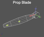
The clockwise and counterclockwise propeller blade models each require a single frame called “~CS_BLADE", which should also be the parent of a collision frame ("~CS_COLL"). It is important to scale the blade so that it has a radius of exactly 1 foot (measured from the origin) in 3ds Max. The ~CS_BLADE frame is rotated and duplicated according to the number of blades that the vehicle’s Engine Component is configured to have.
In addition to the ~CS_BLADE frame, you can create a frame named “HUB” which will contain geometry that is NOT duplicated according to the number of blades.
The pivot of both frames should be positioned at the propeller’s axis of rotation. The frames should in turn be positioned so the pivots are at the origin.
Refer to the screenshots attached to this post for the correct orientation.
Blur Disk Geometry (optional)
(e.g. MyProp PropDisk.kex)
If a blur disk is provided, its filename must end in " PropDisk" (note the space), as shown in the example above.
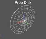
The blur disk requires a single frame called "~CS_BLADEDISK" and does not require any collision geometry. The blur disk pivot should be positioned at the center of the disk. The object should in turn be positioned so the pivot is at the origin.
Refer to the screenshots attached to this post for the correct orientation.
Side View Texture
(e.g. MyProp Side.tga)
This texture is designed to provide a view of the propeller in motion when viewed edge-on. It should include motion blur, and should be carefully matched to the profile of the blur disk shape.
Single Blade Texturing
The clockwise and counterclockwise single blade models are textured as you would texture any other model. They do not support normal or specular maps at this time. Most often, it will make sense for the clockwise and counterclockwise models to share a common texture, although this is not strictly required.
Blur Disk Texturing
The texturing of a blur disk model is handled specially; the UV coordinates specified in the model are disregarded by RealFlight, and new UVs are automatically generated.
The UVs generated will map to a single horizontal row of pixels approximately 15% of the way down the texture. The left side of the row will map to the inside edge of the disk, and the right side will map to the outer edge. In many cases this is effective enough that a special blur disk and texture are not required.
Note that it’s possible to create both variable pitch propellers and folding propellers; however, the specifics are not covered in this initial post. We'll let you know when the full tutorial is available.
Overview
A RealFlight propeller is comprised of several distinct components: a clockwise blade model, a counterclockwise blade model, a blur disk model, and a side view texture. You are not required to provide a blur disk model for a propeller; if the blur disk is omitted, RealFlight will use a default blur disk. Texturing for blur disks is a special case and will be described in more detail later.
The KEX Import Wizard process will prompt you for any one of the three KEX models, then it will automatically locate the other two based on their filenames. You must therefore follow the naming conventions described below for the import to succeed.
The wizard will then prompt for a name and a basis for your propeller. RealFlight's import process will automatically create new KEX and texture files using the name you provide. It is also the name by which the new propeller will be known in the sim.
Once you've imported a custom propeller, you can then select it from the Vehicle Editor for your custom EAs and variants, and it will be included with them when they are exported as RFX files to share with other users.
The orientation of the frames’ pivots, as well as the orientation of the frames themselves in world space, MUST match RealFlight's expectations in order to work properly. Pay close attention to the attached screenshots and the XYZ axes shown.
Single Blade Geometry
(e.g. MyProp_CW.kex, MyProp_CCW.kex)
Both a clockwise and counterclockwise KEX are required. Their filenames must end in _CW and _CCW, respectively, as shown in the example above.
The clockwise and counterclockwise propeller blade models each require a single frame called “~CS_BLADE", which should also be the parent of a collision frame ("~CS_COLL"). It is important to scale the blade so that it has a radius of exactly 1 foot (measured from the origin) in 3ds Max. The ~CS_BLADE frame is rotated and duplicated according to the number of blades that the vehicle’s Engine Component is configured to have.
In addition to the ~CS_BLADE frame, you can create a frame named “HUB” which will contain geometry that is NOT duplicated according to the number of blades.
The pivot of both frames should be positioned at the propeller’s axis of rotation. The frames should in turn be positioned so the pivots are at the origin.
Refer to the screenshots attached to this post for the correct orientation.
Blur Disk Geometry (optional)
(e.g. MyProp PropDisk.kex)
If a blur disk is provided, its filename must end in " PropDisk" (note the space), as shown in the example above.
The blur disk requires a single frame called "~CS_BLADEDISK" and does not require any collision geometry. The blur disk pivot should be positioned at the center of the disk. The object should in turn be positioned so the pivot is at the origin.
Refer to the screenshots attached to this post for the correct orientation.
Side View Texture
(e.g. MyProp Side.tga)
This texture is designed to provide a view of the propeller in motion when viewed edge-on. It should include motion blur, and should be carefully matched to the profile of the blur disk shape.
Single Blade Texturing
The clockwise and counterclockwise single blade models are textured as you would texture any other model. They do not support normal or specular maps at this time. Most often, it will make sense for the clockwise and counterclockwise models to share a common texture, although this is not strictly required.
Blur Disk Texturing
The texturing of a blur disk model is handled specially; the UV coordinates specified in the model are disregarded by RealFlight, and new UVs are automatically generated.
The UVs generated will map to a single horizontal row of pixels approximately 15% of the way down the texture. The left side of the row will map to the inside edge of the disk, and the right side will map to the outer edge. In many cases this is effective enough that a special blur disk and texture are not required.
") Your welcome.
Your welcome.