In the free 6.00.038 update we added support for user-created visual heli blades. We intend to publish a tutorial for this feature on the KEMax section of our website, but for now this should be enough to get you started making your own heli blades.
Overview
A RealFlight visual heli blade consists of three models: a clockwise blade, a counterclockwise blade, and a blur disk. You are not required to provide a blur disk model for a visual blade type; if the blur disk is omitted, RealFlight will use a default blur disk. Texturing for blur disks is a special case and will be described in more detail later.
The KEX Import Wizard process will prompt you for any one of these three models, then it will automatically locate the other two based on their filenames. You must therefore follow the naming conventions described below for the import to succeed.
The wizard will then prompt for a type for your blade (main blade, paddle blade, or tail blade) and a name. RealFlight's import process will automatically create new KEX and texture files using the blade name you provide. It is also the name by which the new blade will be known in the sim.
Once you've imported a custom blade type, you can then select it from the Vehicle Editor for your custom EAs and variants, and it will be included with them when they are exported as RFX files to share with other users.
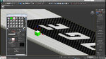
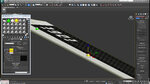
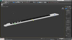
The orientation in world space of single blades and blur disks MUST match RealFlight's expectations in order to work properly. Pay close attention to the attached screenshots and the XYZ axes shown.
Single Blade Geometry
(e.g. MyBlade_CW.kex, MyBlade_CCW.kex)
Both a clockwise and counterclockwise KEX are required. Their filenames must end in _CW and _CCW, respectively, as shown in the example above.
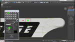
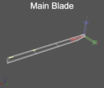
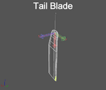
The clockwise and counterclockwise blade models each require a single frame called “~CS_BLADE", which should also be the parent of a collision frame ("~CS_COLL"). It is important to scale the blade so that it has a length of exactly 1 foot in 3ds Max.
The pivot of the blade frame should be positioned at the point where the lead/lag hinge (and therefore the LEADLAG frame on the helicopter model) intersects the blade. The object should in turn be positioned so the pivot is at the origin.
Refer to the screenshots attached to this post for the correct orientation.
Blur Disk Geometry (optional)
(e.g. MyBlade BladeDisk.kex)
If a blur disk is provided, its filename must end in " BladeDisk" (note the space), as shown in the example above.
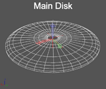
The blur disk requires a single frame called "~CS_BLADEDISK" and does not require any collision geometry. The blur disk pivot should be positioned at the center of the disk. The object should in turn be positioned so the pivot is at the origin.
Refer to the screenshots attached to this post for the correct orientation.
Single Blade Texturing
The clockwise and counterclockwise single blade models are textured as you would texture any other model. They do not support normal or specular maps at this time. Most often, it will make sense for the clockwise and counterclockwise blades to share a common texture, although this is not strictly required.
Blur Disk Texturing
The texturing of a blur disk model is handled specially; the UV coordinates specified in the model are disregarded by RealFlight, and new UVs are automatically generated.
In the event that RealFlight uses the default blur disk model because you did not provide one, it will utilize the single blade texture for the blur disk. In this case, the UVs generated will map to a single horizontal row of pixels approximately 15% of the way down the texture. The left side of the row will map to the inside edge of the disk, and the right side will map to the outer edge. In many cases this is effective enough that a special blur disk and texture are not required.
Overview
A RealFlight visual heli blade consists of three models: a clockwise blade, a counterclockwise blade, and a blur disk. You are not required to provide a blur disk model for a visual blade type; if the blur disk is omitted, RealFlight will use a default blur disk. Texturing for blur disks is a special case and will be described in more detail later.
The KEX Import Wizard process will prompt you for any one of these three models, then it will automatically locate the other two based on their filenames. You must therefore follow the naming conventions described below for the import to succeed.
The wizard will then prompt for a type for your blade (main blade, paddle blade, or tail blade) and a name. RealFlight's import process will automatically create new KEX and texture files using the blade name you provide. It is also the name by which the new blade will be known in the sim.
Once you've imported a custom blade type, you can then select it from the Vehicle Editor for your custom EAs and variants, and it will be included with them when they are exported as RFX files to share with other users.
The orientation in world space of single blades and blur disks MUST match RealFlight's expectations in order to work properly. Pay close attention to the attached screenshots and the XYZ axes shown.
Single Blade Geometry
(e.g. MyBlade_CW.kex, MyBlade_CCW.kex)
Both a clockwise and counterclockwise KEX are required. Their filenames must end in _CW and _CCW, respectively, as shown in the example above.
The clockwise and counterclockwise blade models each require a single frame called “~CS_BLADE", which should also be the parent of a collision frame ("~CS_COLL"). It is important to scale the blade so that it has a length of exactly 1 foot in 3ds Max.
The pivot of the blade frame should be positioned at the point where the lead/lag hinge (and therefore the LEADLAG frame on the helicopter model) intersects the blade. The object should in turn be positioned so the pivot is at the origin.
Refer to the screenshots attached to this post for the correct orientation.
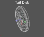
Blur Disk Geometry (optional)
(e.g. MyBlade BladeDisk.kex)
If a blur disk is provided, its filename must end in " BladeDisk" (note the space), as shown in the example above.
The blur disk requires a single frame called "~CS_BLADEDISK" and does not require any collision geometry. The blur disk pivot should be positioned at the center of the disk. The object should in turn be positioned so the pivot is at the origin.
Refer to the screenshots attached to this post for the correct orientation.
Single Blade Texturing
The clockwise and counterclockwise single blade models are textured as you would texture any other model. They do not support normal or specular maps at this time. Most often, it will make sense for the clockwise and counterclockwise blades to share a common texture, although this is not strictly required.
Blur Disk Texturing
The texturing of a blur disk model is handled specially; the UV coordinates specified in the model are disregarded by RealFlight, and new UVs are automatically generated.
In the event that RealFlight uses the default blur disk model because you did not provide one, it will utilize the single blade texture for the blur disk. In this case, the UVs generated will map to a single horizontal row of pixels approximately 15% of the way down the texture. The left side of the row will map to the inside edge of the disk, and the right side will map to the outer edge. In many cases this is effective enough that a special blur disk and texture are not required.
Attachments
Last edited by a moderator: