Physics for true-to-life performace; a Tutorial

Status
Not open for further replies.
The last portion of the wire-frame is to add the landing gear and intake scoops. The scoops are symmetrical fuselage sections attached to the roots of the wings. By now, you shouldn't need my help to do this.

The wire-frame is now complete and the end result should look like the attached picture
 

Attachments

  • Image40.jpg
    Image40.jpg
    123.8 KB · Views: 170
The next step is to adjust the weights of all the components. So far everything has the default weights that RF assigns.

The most accurate way is to do this as you are building a real model. weigh each piece and use those weights. When you don't have that luxury, use a ratio of the overall weight to adjust each component.

So far our model weighs 6.15 lbs. and the target weight (which you can get from a plane manufacture or estimate from similar sized planes) is between 8 & 9 lbs. I'll take the higher end, because I'm using a heavy four-stroke power plant. Picking 8.8 lbs. as the target, you get an adjustment ratio of 1.4:1.

Another method for coming up with a goal weight is to calculate the wing loading based on the type of aircraft. Wing loading for models is measured in oz/sq.ft. Common wing loading values are:

10 Gliders
15 Trainers
20 Sport planes
25 Fighters

Don't trust the wing loading calculations shown in RF. These calculations use all "wing" surfaces, including the tail feathers. The traditional method only uses the area of the main wings, so do the calculations yourself.

There are two ways to set the weights in RF, the first is to go through the editor and multiply all of the weights by 1.4 (except the engine). The second is to just go through the editor and look at all the weights and adjust them until they look right and you get to the target.

Which is the best, I don't know, but a 3.5oz fuselage doesn't make sense to me so I fiddled with the weights individually. I put in better estimates for the retracts and wheels, the wing (because I used three sections) seemed pretty close so I just added 1.5 oz for the servo in each side, the Horz Stab was heavy (because again I used two sections here), the Vert Stab on the other hand seemed a bit light for its size, the scoops were about twice as heavy as they should be for their size, and lastly I made the fuselage 24 oz (which is more reasonable than 3.5).

This gave me a corrected weight of a little under 8 lbs. , closer but still a bit under the target. At this point I looked at the CG (the green cross) for the first time and saw that it was farther aft than it should be.

Well the plane was still a little light and the CG needed adjustment, so I took care of it the same way I would in one of my real RC models. I added a hunk of lead...
 

Attachments

  • Image41.jpg
    Image41.jpg
    101.5 KB · Views: 129
Last edited:
Thanks for putting in the effort and time to make this tutorial. Eventually I hope to contribute with some of my own models and this will be a necessary tutorial for me.

Can we get this stickied possibly?
 
Aeronautical Side Note

Let's talk about the initial placement of the CG for a minute. It's not as critical in the sim as you have the "little red button", but in real life it can make a big difference on your maiden flight.

If you are building an ARF or a kit, always start out with the manufacturer's recommended CG location. Most plans/designs show a CG range. For initial test flights set the CG somewhere in the forward half of that range (i.e. slightly “nose-heavy”). Easy enough, but how do you tell where it should be on that beautiful scratch built scale job that you just spent the last nine months putting together; and you don't have any plans with the CG nicely marked on them?

In this case a little wing theory is necessary.

A typical safe starting point for almost any plane is to have the CG at 25% of the Mean (average) Aerodynamic Wing Cord (MAC). Look at the attached diagram. The MAC is the line shown going across the various wing shapes. The initial CG is shown as being 25% of the total MAC back from the leading edge. A setting at this point should ensure that you at least get your bird back on the ground in one piece after its maiden flight.

Further adjustments are probable, but keep these limits in mind: The farthest back the CG usually gets on a typical trainer is 33%, flying wing and tailless models typically fly with the CG at 15%-20% of the MAC, and few sport or 3D models ever have the CG more than at 40% of the MAC.

As the CG moves aft, the plane becomes less stable in pitch, less sensitive to airspeed changes, and more maneuverable. On the other hand, if the plane is too tail-heavy it’ll become uncontrollable. As a plane gets close to being tail-heavy, the first sign is that the elevator gets touchy and feels as though the elevator trim is inconsistent. For semi-symmetrical/symmetrical wings, if it takes too much down-elevator to fly inverted, the model is likely to be nose-heavy. If it takes no down-elevator, or even climbs sometimes, it is definitely tail-heavy.
 

Attachments

  • Image42.jpg
    Image42.jpg
    50 KB · Views: 90
Last edited:
OK, the plane is now ready for its first flight. But let's pause a moment and talk about what to look for on that first flight. It is not enough to say it flies like &#!^. You need to figure out why it does, so that it can be corrected.

Most of the problems common to many RC aircraft are actually capable of being corrected with minor adjustments (i.e. trim settings). Experienced pilot’s skills may often cover up many of these problems, but they will make it more difficult for a novice. It’s really better, however, for all skill levels to eliminate the problems. After all, even good pilots can look better with a plane that does exactly what it should do.

The kinds of problems that can be fixed:
1) Airplane drastically changes pitch trim with changes in throttle and airspeed.
2) Airplane does not settle into a predictable glide slope when throttle is reduced.
3) A tendency to veer off in one direction (usually left) when climbing or when full power is applied.
4) Poor aileron control response (especially at low airspeed) and directional trims that change with airspeed.

Since aerodynamics is a constant balancing act of several forces (lift, gravity, and engine thrust), there is often more than one potential cause for any particular problem. The real task is that you have to figure out what needs to be adjusted.

Over the next few test flights, I'm going to show you a systematic method for setting up and trimming a model plane. This method not only works in the sim but it will also work for you in real life.

At this point you may use the AV you've been working on, or fly along on the one I've been building for this tutorial.
 

Attachments

  • Image43.jpg
    Image43.jpg
    48 KB · Views: 85
  • Tutorial_AV.G3X
    20.9 KB · Views: 45
Last edited:
On the first flight test, we'll focus on pitch adjustments.

Once the plane is trimmed for level cruise (at about 3/4 power), do a couple of simple tests.

Test 1: Smoothly advance the throttle to full. Without making elevator corrections, but still keeping the wings level, watch the climb that results.

Is the climb too shallow & fast? This might be fine for a sport plane, but for a trainer the climb should be solid with adequate airspeed.

Is the climb too steep? Watch to see if the climb is so steep that the airspeed is decayed.

Has aileron control become sloppy and it is difficult to promptly correct for wind effects? That is a sign that the airspeed has become too slow due to the steepness of the climb.

General Solution: To reduce the steepness of the climb and make the airplane less speed sensitive you can either move the CG aft and add down-elevator trim or add down-thrust to the engine. Now if the plane climbs too shallowly, you'd want to do the opposite.

To decide whether to change the down thrust or CG point, we'll go to the next test.

Test 2: Perform a low-throttle glide test. Set up a straight and level pass, parallel to the runway and roughly 100’ up. Trim for cruise power level flight and with your hand off of the elevator stick, quickly reduce power to one or two clicks above dead idle (final approach speed) just before the plane passes. Watch the glide slope that results, again keeping the wings level but making no elevator corrections.

Does the model settle into a nice glide, or does it come down like a rock, or is the glide slope so shallow that the plane wallows along at a near stall?
 
Last edited:
Now that both pitch tests have been performed, take what you have observed to make changes to the plane's setup.

Look at the trim settings you had to dial into your controller. If the elevator had to be trimmed level or slightly down for level flight, the model has insufficient down thrust. Alternatively, if the elevator had to be trimmed up, the plane is nose-heavy.

If the model needs more down-thrust, at full power it will climb too steeply. It will also glide too steeply when the nose-up engine thrust is removed and the down-trim or nose–heaviness takes over.

It is also possible that the plane climbs too steeply under full power and glides OK or even a little steep if the model is nose-heavy. To tell if this is the case, again look to see if the elevator was trimmed up for level flight (even a little bit), showing that the plane was nose-heavy and that trim was needed to counteract it.
 
Putting the results of the first flight test all together, to determine which pitch adjustment to make:

The climb or glide is too steep and the elevator trim is up.

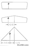
The trick to telling the difference between nose-heaviness and insufficient down-thrust in a model that climbs too steeply under full power is to look at the elevator trim. If the plane carries up-trim, move the CG back 1/4" and retrim the elevator for level cruise and do the tests again.

Once the climb and glide rates are acceptable, even though there may be a bit of down-trim, stop there.

If you have to move the CG back far enough that down-elevator trim becomes necessary for level cruise, move the CG forward the last step and start adding down-thrust.

The climb or glide is too steep and the elevator trim is near neutral.

If the plane had no noticeable up-trim to begin with, add down-thrust.

If at any point the model gets touchy in pitch, the plane is too tail-heavy, move the CG back to the last location where the elevator control was predictable. If the plane still needs a great deal of elevator trim to fly level, change the wing incidence. This may require some time in the shop for a real RC plane, but it's an easy thing to do with the simulator. That's one of the reason I like to model each plane I build for real in the sim, before I finish assembly. If it needs a lot of up-trim, shim the LE of the wing (high-wing). If it needs a lot of down-trim, shim the TE of the wing (also high-wing). Use small steps to avoid drastic or unpredictable consequences. In the sim, increase the incidence of the main wing 1/2 to 1 degree at a time and retest.

The climb or glide is too steep and the elevator trim is down.

The most likely cause of this is that the wing and/or stabilizer incidences are wrong and creating a strong nose-up tendency, which gets worse at high airspeed. This is a sign that the plane has excessive pitch stability and/or excess horsepower.

Trainers are intentionally stable but do not tolerate overpowering well. In this case the cure is not to have less power, but put the plane in “low gear” with a prop that limits the top airspeed. A larger-diameter, low-pitch prop or a three-bladed one of the same diameter and lower pitch will help limit the excess airspeed while harnessing the same power.

The climb or glide is too shallow and the elevator trim is down – even a little.

If the model climbs well (or even a bit shallow) at full throttle and then glides nicely (or a bit shallow), and you want the plane to change trim with airspeed more than it does. Look at the elevator trim to tell whether or not you should reduce the down-thrust or push the CG forward. Start by moving the CG forward to get rid of the down-trim, and then reduce the down-thrust. Move the CG forward, retrim for level cruise and retest. Continue making adjustments until the elevator trim is nearly level, then move on to adjusting the down-thrust.

The climb or glide is too shallow and the elevator trim is level, or even a little bit up.

If the elevator was not trimmed down, the CG is not the issue. Reduce the down-thrust.

Alternate test for Sport Planes:
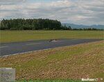
Set up a hands-off level pass about 50’ off of the deck, suddenly pull the power to idle. For a second or two the plane will still be zipping along at cruise speed. The down-thrust will have been taken out of the equation and aerodynamic forces will predominate.

If the nose twitches up and the model slows into a glide, you have too much down-thrust.

If the nose abruptly drops a tiny bit and the plane instantly assumes a fast, nose-down glide, you need more down-thrust. This is because the trim has been fighting down against an engine induced climb.

If the down-thrust is correct, the plane will continue straight for a second or two and then gradually fade into the glide angle.

It is also possible to see the effect of incorrect down-thrust when power is applied. In cases where much more down-thrust is needed, the plane may abruptly nose-up when power is fire-walled for a go around.
 
Last edited:
In flight testing my Spit, it seems that the CG and thrust were pretty much perfect. But I've been doing this for a very long time. :)

No adjustment to the CG, trim, or prop were necessary. The math and diligence in picking airfoils paid off...
 
Now that the plane has been trimmed for pitch and has a proper glide, we'll move on to looking at directional control.

One of the most common problems observed at the flying field is planes that take off and immediately veer to the left.

Test 3: Set the plane up so that it is flying straight away from you and headed either directly into the wind or directly downwind. A crosswind in this case will hide the turn you are looking for. Add full throttle and smoothly pull into a climb, at the same angle as a steep post-takeoff climb. In all likelihood the model will start to turn.

If the plane deviates to the left, more right-thrust is needed.

If the plane has too much right-thrust (fairly uncommon), it will deviate to the right.

If the right-thrust is close you may have to repeat the test a couple of times to see which direction it tends to.

Most model airplane pilots never really master accurate and independent control of the rudder, so right-thrust is a compromise to counteract an airspeed-dependant problem.

At low and partial throttle the effect of right-thrust is minimal. So we set the right-thrust to straighten out a full-power takeoff climb and accept the small, unwanted influence it has at cruise. So engine right-thrust corrects for the engine’s torque, which makes the plane turn left during climb.

It is best to adjust the right-thrust angle one degree at a time and repeat the process. Most planes will require 2°-3° of right-thrust, although a rare few need much more.

On the next flight, retrim for straight and level (probably just a click or two of rudder) and test again. Repeat until the plane climbs straight.
 
Last edited:
Aeronautical Side Note

Actually, the word torque is a misnomer (but it is a convenient catchall). The primary cause of "torque" is the spiral airflow that comes off of the prop. There are two other sources – the “P” factor and the pure torque of the engine – but they are small contributors.

If you held a streamer behind a spinning prop, you’d see a corkscrew path in the same direction as the prop rotation. This airflow strikes the left side of the fin and rudder (which is usually above the thrust line) and yaws the plane left. As the plane accelerates, the pitch of the corkscrew pattern gets straighter, so that the torque effect is greatest at low speed and high throttle.
 
Saving your trim settings

As you are doing your flight tests and adjusting the trims on your controller, you need a way to permanently save the settings. Well the RF controller doesn't have digital trims that will be remembered between models. But the RF program does...

Here's how to save the settings:

Say you've just finished a test flight and had to put in a couple of clicks of right rudder. Before you reset the trim on your controller, open the plane in the editor. Go to the software radio for the channel(s) you added trim to.

At the bottom on the page for the channel is a number for the current value of the channel. Remember this number and zero your trim for the channel. The current value will go to zero (or very close to it). Now in the top field for trim, invert the sign and type the same number here. The display will round to the nearest whole number but your value will go into the system and be stored with the aircraft.
 

Attachments

  • Image44.jpg
    Image44.jpg
    72.8 KB · Views: 99
  • Image45.jpg
    Image45.jpg
    80.3 KB · Views: 96
The topics of pitch trim, getting a good glide, and correcting for torque effects have all been addressed. There are two more directional control issues that effect planes in the simulator. They go hand-in-hand with the trimming for torque effects, but there is no good way to address all issues simultaneously.

The first problem is known as cross-trim. The direction of the aircraft can be controlled by either the rudder or the ailerons, but these two control surfaces do not behave the same way. When a plane is cross-trimmed it also behaves differently turning left vs. right.

Let’s say the model has the rudder offset to the right to correct for the small yaw induced by adding left thrust to the engine. The ailerons will need to be trimmed left to fly in a straight line (in fact the plane will be crabbing to the right). When this plane is turned left it will tend to hang its nose “out of the turn” and may even tend to roll back to level flight. When turned to the right, however, this same model will tend to roll harder into the turn and even try to roll over into a spiral dive.

To correct the cross-trim, make left and right turns (with the same angle of bank) and adjust the rudder away from the direction of turn that the plane rolls into the turn. Every time you adjust the rudder, retrim the ailerons for level flight. When you think that you have it right, try a long glide at idle power as a fine-adjustment test. If the model wanders off to one side tweak the rudder trim to correct and retrim the ailerons again.
 
Last edited:
The second directional control problem that effects planes in the simulator is known as adverse yaw.

This problem often gets worse at low speeds and high angles of attack, in other words - when you least want it. What happens is this: Say you want to apply right bank to exit a left turn. The desired result will be to lift the left wing and lower the right. Wings are not very heavy, but it does takes more energy to raise a wing than it does to lower one. The energy needed to raise the wing comes from drag. This means that the left wing that is being raised has more drag and it tries to yaw the plane in the wrong direction (i.e. adverse yaw).

There are three ways to correct adverse yaw. The first is to do what full-scale pilots do: always use rudder along with ailerons. It’s called a coordinated turn and it is a basic flying skill. While this is a skill most RC pilots would do well to learn, it is often too much for a novice to handle. The second thing is to couple the ailerons into the rudder. So that when right aileron is applied, right rudder is also. This can be done mechanically or with a programmable radio mix. Typically, full aileron throw only requires roughly one-quarter rudder. The third and preferred method is to use aileron differential. Some coordinated rudder may still be necessary during the steepest climbs, but a differential setting that is good for the entire flight profile can usually be found. Many full-scale aircraft are even manufactured to use differential ailerons. For example, a Piper Cub has nearly twice the aileron travel in the up direction.

A typical low-wing sport model usually needs the ailerons to move up about 20% more than they move down. A good starting point for high-wing trainers, however, is about 50%.

Aileron differential is easy to describe but may require a little effort to set up in a real RC plane (I'll cover this at the end of the thread). In simple terms, when you move the ailerons, the aileron that goes up must travel farther (in degrees) than the one that goes down. Modern radios can do this with programming if two servos are used for the ailerons. The mechanical method is to use creative offset linkages to control the ailerons.
 
Last edited:
The test to see whether you need to add differential aileron throws is called a Dutch Roll.

Fly in a straight line away from yourself at a safe low altitude. Smoothly rock the plane from side to side, banking the plane at about 45° each way. Use as much aileron as you can while comfortably keeping up with the plane. One of three things will happen:

1) Axial Rolling. The plane will roll back and forth and the tail will point straight at you and not wiggle at all. That means the differential is perfect for level flight.

2) Adverse Yaw (typical). The model “duck walks”, with the tail wiggling right as you turn right. This means that the nose is going the wrong way and more differential or aileron-into-rudder coupling is needed.

3) Proverse Yaw (uncommon). The nose turns in the same way the plane banks. The tail swings out as if starting a sudden turn. This is not great for aerobatics, but it is perfectly acceptable for a trainer. It adds stability and control during all positive-G flight. If you decide to adjust it, reduce the differential or aileron-into-rudder coupling.

Retest the Dutch Roll test in a climb to uncover any adverse yaw problems that may require a lot of differential.
 
Last edited:
bobbaker said:
No offense sir, but your UltraStick really flies like poo-poo.
I own one and it flies no where near that. So why are you wasting your time posting this doodie?
I read through the entire damn thing and it don't help me out one ding, dang bit!

Regards,
Mr. Baker
Just saying something flies bad is not much help. You have to let someone know how it flies bad.

You say it doesn't fly like yours and that may or may not be a problem. I've owned three of them and think it's a pretty fair representation, but then the G3 model is set up the way my favorite real one was (overpowered with lots of extra control throw). When that plane was modeled over a year ago, there was a lot of discussion from other real UltraStick owners. Most felt the model was very accurate. Now if you would like an AV that matches yours more closely, maybe we can work something out.
 
To set up differential ailerons in the sim, open the software radio section. The ailerons on this model are on channels 1 & 5. Note that you do need to have two ailerons servos in order to do this.

In the first picture the ailerons move symmetrically, up & down the same amount. Delete the inputs under each channel. Replace the simple inputs with complex inputs. Open the response graph and edit the end that corresponds to the aileron moving down (picture 2). Now in picture 3, you can see that the left aileron has moved down only half as much as the right one has moved up.

Note that this is an excessive amount of aileron differential for this particular plane, but I wanted the difference to be visible in the picture.
 

Attachments

  • Image46.jpg
    Image46.jpg
    81.8 KB · Views: 91
  • Image47.jpg
    Image47.jpg
    115.1 KB · Views: 96
  • Image48.jpg
    Image48.jpg
    85 KB · Views: 77
Last edited:
bobbaker said:
No offense sir, but your UltraStick really flies like poo-poo.
I own one and it flies no where near that. So why are you wasting your time posting this doodie?
I read through the entire damn thing and it don't help me out one ding, dang bit!

Regards,
Mr. Baker
Your such a lil' baby,go get your binky and shuuuut uuuup. :D
P.S POO Does Not Fly.
 
Thank you for the tutorial DHK,i'm confused tho,i'm not sure how you line up/shape the fuse. :confused: :eek:
You were wright on the F-16,i went crazy with the weight! :eek:
I have gotten better now,try out the kingcat composite AV,it flys nice,really smooth too not crazy with speed,200mph,thats ok for jets! Bibplane and 200mph=What kinda turbine is in your turbo toucan!?!? :D
 

Attachments

  • ScreenShot1183761352.jpg
    ScreenShot1183761352.jpg
    262.3 KB · Views: 58
Last edited:
That pretty much finishes the trim topics that can effect the simulator's physics. There are, however, some other problems that can have an affect on real RC aircraft. Most of these problems have their root in the construction of the airplane.

The first problem occurs mostly at low-speed and high angles of attack, and has probably contributed to more RC landing mishaps that all other causes combined. The problem is uneven aileron hinge gaps (this is not a problem in the simulator). It occurs very unpredictably, but when it occurs you often do not have time to recover (i.e. landing). It is better to fix this problem before it ever bites you and the fix is easy. Just seal the gaps between the ailerons and the wing, so that the higher pressure air from under the wing cannot pass through the gap. It only takes a couple of minutes to use tape or monocote to create the seal, before you take a bird out for its first flight. It's cheap insurance...

The second problem is lateral (side-to-side) balance. The instructions for most ARFs (and kits too) only tell you to balance the plane from end-to-end to set the CG, but the lateral balance is important too (especially if you want to do more than fly around in a level pattern). The lateral balance is only effected by gravity and so it does not change with airspeed, but it will cause the plane to roll towards the heavy side in “High-G” maneuvers (i.e. loops). The solution to keeping the plane balanced at all speeds is to have the aircraft weight balanced from side-to-side. The easiest way to do this is to take the prop off and suspend the plane from the prop shaft and a cord passed under a rudder hinge (use the hinge closest to, but above the aircraft center of mass). Add weight to the high side until you get the plane to balance.

The third problem is imperfect airfoils. These are tiny differences in airfoil shape (especially the rounding of the LE) that can require that the ailerons be trimmed to counteract. The aileron deflection and resulting airfoil shape will have different airspeed characteristics, so the required trim will change with airspeed. There is not much that can be done about this after the fact, so use care if you are building a kit.

The last problem is wing warps, even subtle ones. These also require aileron trim to counter and vary with airspeed. A warp will usually maintain its influence at very low speeds, however, while any aileron trim loses effectiveness. Some minor wing warps can be fixed, if the wing is covered in heat shrink covering. Have someone twist the wing in the opposite direction of the warp and small creases will appear in the covering. While the wing is being held, use a heat gun to shrink out the creases. As the covering cools, it will hold against the warp and hopefully flatten out the wing.
 
Last edited:
Status
Not open for further replies.
Back
Top