
Boof69
Well-known member
Required Parts Naming Convention
Notice that all required part names and any others that you would like to break off during
a crash must have the ~CS_ prefix. This prefix adds the part to the components list found
under any added wireframe part in the RF editor.
~CS_ENGINE
is a required part that is necessary for positioning the Prop in RF.
The pivot of this object determines the rear most face of the prop.
(The object you use is not important only the pivot.
Therefore even a dummy object can be used.)
~CS_SPINNER
is required only if you don't want a warning message to appear.
Also if you add a number to the ~CS_ENGINE object that same
number must be assigned to the ~CS_SPINNER object.
IE: ~CS_ENGINE1/~CS_SPINNER1.
This would usually only be necessary in multiple engine scenarios.
~CS_LG,~CS_LW Left Gear and Wheel
~CS_RG,~CS_RW Right Gear and Wheel
~CS_SG,~CS_SW Steering Gear and Wheel
Are the minimum for a proper gear and wheel setup. This is how
the sim understands to spawn and orientate the model correctly.
~CS_GD(1-4)
These names are required for gear doors and the suffixed number
tells the sim what opening and closing behavior the door will have.
More information on these behaviors here
Gear NUP values explained.
To set up retractable gear correctly NUP values should be placed in both the landing gear and gear door object's
properties under "user defined". Setting these values before a kex export automates the process
in RealFlight so that simply adding a gear component and then assigning a retract servo makes everything work.
There are only 2 NUP values to learn "NUP_MaxRotation" and NUP_LandingGear.
NUP_MaxRotation sets the rotation of that object in degrees in the specified axis and is required in both
the landing gear and gear door objects. So for example if my landing gear rotates up into the wing
using the Y axis and it rotates 87.5° The NUP line would be as follows:
NUP_MaxRotationY=87.5
NUP_LandingGear sets up the dependency of landing gear for the gear door and therefore is only used in the
gear door objects. So for example a gear door positioned on the outside of the left landing gear rotating on the Y axis rotating -93°
would need the following NUP values:
NUP_MaxRotationY=-93
NUP_LandingGear=~CS_LG
Proper syntax is required for these lines so pay attention to capitalization and leave no spaces.
~CS_SG_SPRING
This is not a required part but if you want a springy behavior for the
tail gear this part can be put between the fuselage and the ~CS_SG
component.
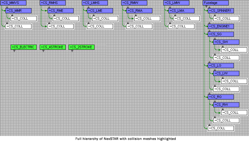
~CS_COLL
Use this as a prefix for all collision mesh objects. Adding an _? will help
delineate each collision mesh object for better organization.
As a suggestion use the name of the part it will be a child of.
For example the collision mesh for the ~CS_RMW would be ~CS_COLL_RMW.
All other parts are not required names at least in my experience but I do follow KE's suggested
naming for all other parts. This link has clear examples of this naming convention for most
possible models.
Required Material Naming
~ALPHA
This tells the sim to pay attention to the alpha information contained in the TGA
~SBS(Show Both Sides)
This tells the sim to display the material on both sides of a poly.
~CANOPY
This combines the aspects of ~ALPHA and ~SBS and is most useful on
glass objects.
~BREAKAPART
This material type is used to not render unless the part or parts using this material
break off from the rest of the model.
I have tried this but never noticed if it works or not. I believe it's purpose is
to lighten the load on the render engine.
Other Naming
~CS_GLOW
This name is given to extra geometry that will automatically glow when the sun is
down in the sim. These parts do not render in lighted conditions.
~CS_BULB
Just like glow objects bulb objects will glow when the sun is down, but they do
render during the day. They also are programmable to make them blink and can be
sequenced with other lights for some impressive effects. If programmed to, these
bulb objects can be given a steady glow and in my opinion renders glow objects
obsolete.
Since the NUP values for bulb objects are hard to find they are as follows.
NUP_OffPeriodSEC=0.5(This sets how long the bulb we be off.)
NUP_OnPeriodSEC=1.0(This sets how long the bulb will be on)
NUP_OffsetSEC=.75(This sets the time to wait before starting the on/off sequence again)
Proper syntax is required for these lines so pay attention to capitalization and leave no spaces.
Engine to Show Feature
is designed to allow for multiple engines to be shown. The end user could select
an electric motor, 2 stroke or 4 stroke engines, or even no engine at all if all types
of power plants were included for that model. This feature is found in the aircraft editor
, if "Advanced' is selected under <options/display properties>, under the "engine" component.
However this feature can be used to hide and show any geometry the designer chooses.
The key is simply in the naming of the objects. Technically you have 4 choices but the fourth is
to show nothing. "NONE". The visible choices are:
~CS_MOTOR
~CS_2STROKE
~CS_4STROKE
Any objects that you choose to name accordingly will show up in the "engine to show" feature
and only the selected part will show up.
For instance I recently made a model with 2 different canopies. I named one ~CS_2STROKE and the other
~CS_4STROKE. This worked flawlessly.
Notice that all required part names and any others that you would like to break off during
a crash must have the ~CS_ prefix. This prefix adds the part to the components list found
under any added wireframe part in the RF editor.
~CS_ENGINE
is a required part that is necessary for positioning the Prop in RF.
The pivot of this object determines the rear most face of the prop.
(The object you use is not important only the pivot.
Therefore even a dummy object can be used.)
~CS_SPINNER
is required only if you don't want a warning message to appear.
Also if you add a number to the ~CS_ENGINE object that same
number must be assigned to the ~CS_SPINNER object.
IE: ~CS_ENGINE1/~CS_SPINNER1.
This would usually only be necessary in multiple engine scenarios.
~CS_LG,~CS_LW Left Gear and Wheel
~CS_RG,~CS_RW Right Gear and Wheel
~CS_SG,~CS_SW Steering Gear and Wheel
Are the minimum for a proper gear and wheel setup. This is how
the sim understands to spawn and orientate the model correctly.
~CS_GD(1-4)
These names are required for gear doors and the suffixed number
tells the sim what opening and closing behavior the door will have.
More information on these behaviors here
Gear NUP values explained.
To set up retractable gear correctly NUP values should be placed in both the landing gear and gear door object's
properties under "user defined". Setting these values before a kex export automates the process
in RealFlight so that simply adding a gear component and then assigning a retract servo makes everything work.
There are only 2 NUP values to learn "NUP_MaxRotation" and NUP_LandingGear.
NUP_MaxRotation sets the rotation of that object in degrees in the specified axis and is required in both
the landing gear and gear door objects. So for example if my landing gear rotates up into the wing
using the Y axis and it rotates 87.5° The NUP line would be as follows:
NUP_MaxRotationY=87.5
NUP_LandingGear sets up the dependency of landing gear for the gear door and therefore is only used in the
gear door objects. So for example a gear door positioned on the outside of the left landing gear rotating on the Y axis rotating -93°
would need the following NUP values:
NUP_MaxRotationY=-93
NUP_LandingGear=~CS_LG
Proper syntax is required for these lines so pay attention to capitalization and leave no spaces.
~CS_SG_SPRING
This is not a required part but if you want a springy behavior for the
tail gear this part can be put between the fuselage and the ~CS_SG
component.
~CS_COLL
Use this as a prefix for all collision mesh objects. Adding an _? will help
delineate each collision mesh object for better organization.
As a suggestion use the name of the part it will be a child of.
For example the collision mesh for the ~CS_RMW would be ~CS_COLL_RMW.
All other parts are not required names at least in my experience but I do follow KE's suggested
naming for all other parts. This link has clear examples of this naming convention for most
possible models.
Required Material Naming
~ALPHA
This tells the sim to pay attention to the alpha information contained in the TGA
~SBS(Show Both Sides)
This tells the sim to display the material on both sides of a poly.
~CANOPY
This combines the aspects of ~ALPHA and ~SBS and is most useful on
glass objects.
~BREAKAPART
This material type is used to not render unless the part or parts using this material
break off from the rest of the model.
I have tried this but never noticed if it works or not. I believe it's purpose is
to lighten the load on the render engine.
Other Naming
~CS_GLOW
This name is given to extra geometry that will automatically glow when the sun is
down in the sim. These parts do not render in lighted conditions.
~CS_BULB
Just like glow objects bulb objects will glow when the sun is down, but they do
render during the day. They also are programmable to make them blink and can be
sequenced with other lights for some impressive effects. If programmed to, these
bulb objects can be given a steady glow and in my opinion renders glow objects
obsolete.
Since the NUP values for bulb objects are hard to find they are as follows.
NUP_OffPeriodSEC=0.5(This sets how long the bulb we be off.)
NUP_OnPeriodSEC=1.0(This sets how long the bulb will be on)
NUP_OffsetSEC=.75(This sets the time to wait before starting the on/off sequence again)
Proper syntax is required for these lines so pay attention to capitalization and leave no spaces.
Engine to Show Feature
is designed to allow for multiple engines to be shown. The end user could select
an electric motor, 2 stroke or 4 stroke engines, or even no engine at all if all types
of power plants were included for that model. This feature is found in the aircraft editor
, if "Advanced' is selected under <options/display properties>, under the "engine" component.
However this feature can be used to hide and show any geometry the designer chooses.
The key is simply in the naming of the objects. Technically you have 4 choices but the fourth is
to show nothing. "NONE". The visible choices are:
~CS_MOTOR
~CS_2STROKE
~CS_4STROKE
Any objects that you choose to name accordingly will show up in the "engine to show" feature
and only the selected part will show up.
For instance I recently made a model with 2 different canopies. I named one ~CS_2STROKE and the other
~CS_4STROKE. This worked flawlessly.
Last edited:
") Included!
Included!