Quicker and Easier Mapping in 3ds Max

Boof69

Well-known member
I have been playing around with the UV mapping tools and I feel I have come up with a better way to map and this is how I will be doing it from now on. Even if you are happy or accustomed to the way you map I urge you to at least watch the video.
I am not posting this in my tutorial sticky at this time because it is out of sequence. I will add it or even make a longer video on this method in the future. I hope this makes mapping easier for you. The video is loud be warned. Sorry about that.
 
You downloaded a youtube video?
Yes I downloaded the video from YouTube I've downloaded lots of your videos. I have a whole section of Boof69 information, posts and videos. Ha.. If you had a nickel for everything I've downloaded of yours you'd probably have a couple of bucks by now. <grin>
 
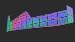
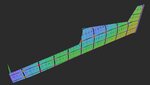
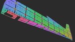
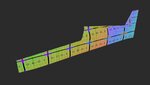
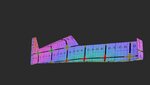
So I played with this method tonight with mixed results. I first followed the video step by step and got horrible results. Then I realized you had one half of the fuse deleted, and I was mapping the whole fuselage. After deleting half of the fuselage, I got very similar results. The initial results after the peel is applied can be seen in the last 3 pics. It has a little distortion along the top of the fuselage, and the vertical stab is blown out of scale, but those are both fixable. However, with this fuse having cutouts on the bottom, this method really didn't seem like it was going to work like I would like it to. I began to think it is going to be better to map the bottom as it's own object. So, I was about to give up on using this method until I noticed there was a flatten by polygon angle option. What could it hurt to try, right? Well, this method actually give me almost exactly what I feel is going to be the best option on the bottom. This one even separated the inner and outer sections of the fuselage, and has very little distortion to repair. Big downfall to this one is it actually breaks all of the faces that make up the depth of the cutouts into separate pieces, so I'll have a lot of work there to fix that. These results are in the first three pics below.

All in all, I think I'm really going to like this method for the average build. However, If there are cutouts for landing gear, or vents as in my case, there may be unforeseen issues that will make it more difficult to map. But, for right now, I'm going to keep working with this method and maybe I'll find where I made a mistake or something giving me these difficulties.
 

Attachments

  • 1.jpg
    1.jpg
    291 KB · Views: 11
  • 2.jpg
    2.jpg
    234.7 KB · Views: 12
  • 3.jpg
    3.jpg
    331.6 KB · Views: 12
  • 4.jpg
    4.jpg
    197.2 KB · Views: 12
  • 5.jpg
    5.jpg
    208.9 KB · Views: 9
  • 6.jpg
    6.jpg
    200 KB · Views: 8
I think it has to do with your fuse having a flat bottom.
I believe if you would have made the bottom of the fuselage a separate smoothing group to start It would have mapped correctly.Then been re-attached as the turtledeck was in the video. Then change the smoothing group as necessary.
As for the little pieces that make up your cutout, that's not a downfall. There is no way to easily map elements like that. I did show how quickly the stitch custom button works to select an edge and in one click they come together and weld.
 
Last edited:
I’ll try changing the SGs and see what happens. And yeah, I’m working on the stitching. Think I’ve about got it down.
 
In the case of those small parts, will you be attaching them back to the cutouts on the fuse and 45ing the corners or laying them out as strips separate from everything?
 
I’ve got things going my way with this. I’d like to mention that careful thought/planning needs to be done on more complex areas. For example, the bottom of my fuselage has the vents cut out with faces creating thickness of the fuselage. I gave those faces the same SG as the bottom fuselage to have them all as one piece. Once I peeled, the bottom turned out like a horseshoe. Apparently, peel tries not to distort faces as much as possible so that spread out the area of the vents causing the warp I was seeing. I then applied all the depth faces their own SG. Warping was fixed, but all sections of depth faces were one object on the map and couldn’t be applied to their respective vent hole. The fix is each individual section has to have their own SG in order to be placed correctly with the stitch custom command.

Another example, I’ve still got the vertical attached to the fuselage. At the joint with the fuse, there’s a bevel. Applying the vert and fuse one SG has the same stretching effect due to the faces making up the bevel. To fix that, either the vert or the fuselage gets the same SG as the bevel, while the other gets its own SG.
 
Remember too that if you set up smoothing groups on the model and they don't agree with the peel you can create a seam within the UV mapping as I did with the tire in the video. This is what allowed the tread to be layed out flat as one piece even though the entire tread was one smoothing group.
 
Is there a video how to do a basic map in 2019 naming and uv? I seem to be crashing the Sim I get to the point to load dynamics but i get a map crash.
 

Attachments

  • Siti.zip
    1.9 MB · Views: 4
Back
Top