We've mentioned elsewhere that the new InterLink DX is not fully supported in RF8 but that it should still be usable despite some limitations. Namely, the many 3-position switches will only work as two position switches, and high-speed input from the scroll wheel will be spotty at best.
I've seen some posts lately from people having trouble with the DX in RF8, so I thought a detailed post might help. Here are the steps I took just now running through this for the first time. You may decide to make some different choices than I did, and that's okay, but hopefully by the end of this post you will have an understanding to inform those decisions.
The three-position switch limitation can really be felt with certain vehicle setups, such as helis with three flight modes (normal, idle up 1, & idle up 2), or airplanes with three AS3X or similar flight modes, or drones with three advanced flight modes, or models like the P-51 Mustang where both smoke and the actuating canopy are mapped to channel 8. There is no getting around that drawback on the hardware side, but remember that the Virtual Channels offer a way to supplement the available controller inputs and provide that finer level of control.
I've seen some posts lately from people having trouble with the DX in RF8, so I thought a detailed post might help. Here are the steps I took just now running through this for the first time. You may decide to make some different choices than I did, and that's okay, but hopefully by the end of this post you will have an understanding to inform those decisions.
- Connect your InterLink DX and start RealFlight 8.
- From the Simulation menu choose Select Controller...
- If you have more than one controller connected, click to select the InterLink DX.
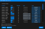
- Start at the top, in the Controller Setup section.
- Click the Edit button to begin customizing the radio profile. (It should have defaulted to the Gamepad profile, but in this case it doesn't really matter because we're going to redo everything.)
- For Channel 1, click the input button (it probably says "Dial" currently) and move your aileron stick. Direction doesn't matter. Just be careful not to bump any other inputs, because you don't want it to "hear" the wrong one.
- For Channel 2, click the input button (it probably says "Z Axis" currently) and move your elevator stick. The same notes from Ch1 above apply here and to all subsequent channel mapping steps.
Also, uncheck the Reverse option. - For Channel 3, click the input button and move your throttle stick.
Also, uncheck the Reverse option. - For Channel 4, click the input button and move your rudder stick.
- For Channel 5, click the input button and move your dual rates switch. I chose to use Switch C.
Important note 1: If you choose a three-position switch like I did, you should first move it to either the center position or the up/down position you wish to use, then click the input button and move it in the desired direction. In my case, I want to use the up position for high rates and the middle position for low, so I moved the switch into one of those two positions before assigning the input. If it starts out in the down position, then you will end up mapping the center and down positions to the new channel instead of center and up. But not to worry if that happens; simply adjust the switch position as needed and click the input button again to remap it.
Important note 2: After mapping the input to your satisfaction, expand the dropdown control and change Toggle to Proportional. - For Channel 6, click the input button and move your flaps switch. I chose Switch D. See the Important Notes for Ch5 above. They apply to all subsequent numbered channel mappings.
- For Channel 7, click the input button and move your smoke switch. I chose Switch F.
- For Channel 8, click the input button and move your mode switch. I chose Switch B.
- For Channel 9, click the input button and move the left slider on the rear of the controller.
- For Channel 10, click the input button and move the right slider on the rear of the controller.
- I chose not to map channels 11 & 12 at this time because no stock models use them as inputs.
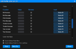
- Scroll down to the Trims section.
- For Roll Increase, click the input button and move the aileron trim to the right.
- For Roll Decrease, click the input button and move the aileron trim to the left.
- For Pitch Increase, click the input button and move the elevator trim up.
- For Pitch Decrease, click the input button and move the elevator trim down.
- For Throttle Increase, click the input button and move the throttle trim up.
- For Throttle Decrease, click the input button and move the throttle trim down.
- For Yaw Increase, click the input button and move the yaw trim to the right.
- For Yaw Decrease, click the input button and move the yaw trim to the left.
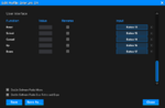
- Scroll down to the User Interface section.
- For Reset, click the input button and press your Reset button.
- For Select, click the input button and depress your scroll wheel. Be careful not to roll it left or right in the process. If that happens, simply click the input button again and remap it.
- For Cancel, click the input button and press your Cancel button.
- For Up, click the input button and roll your scroll wheel to the left. Note that it may take a bit of rolling before it is detected.
- For Down, click the input button and roll your scroll wheel to the right. As above, note that it may take a bit of rolling before it is detected.
- Look back up through the list of all the controls you have mapped. Other than anything you deliberately left unmapped, make sure no channels show Unassigned for their input. That can happen if you accidentally bump an already-mapped control during a later mapping step for a different channel. When that happens, it unmaps it from the originally assigned channel. The fix is simply to remap it in the desired original location.
- Click Save As...
- Enter InterLink DX as your new radio profile name and click OK.
- Click Close.
- Back at the Select Controller dialog, click Calibrate, and follow the instructions. For this type of controller you only need to move the two sticks and the two rear sliders to their extents.
- When you click to finish calibration you will receive a warning message about only 6 of the 8 axes being calibrated. That is normal for this particular situation. Click Yes to proceed.
The three-position switch limitation can really be felt with certain vehicle setups, such as helis with three flight modes (normal, idle up 1, & idle up 2), or airplanes with three AS3X or similar flight modes, or drones with three advanced flight modes, or models like the P-51 Mustang where both smoke and the actuating canopy are mapped to channel 8. There is no getting around that drawback on the hardware side, but remember that the Virtual Channels offer a way to supplement the available controller inputs and provide that finer level of control.