Super Gee II

CS question time.

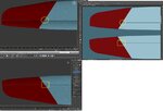
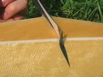
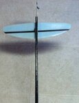
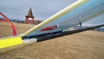
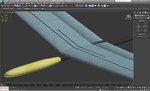
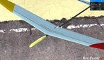
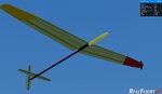
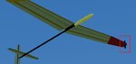
An angled straight edge across the wing/aileron gap on the tga map does not follow the same straight edge on the model. The alignment error is more noticeable on the bottom side. Is the solution to use two lines and adjust their end positions at the gap as needed?


Thanks
 

Attachments

  • SG2 tip color.jpg
    SG2 tip color.jpg
    472.8 KB · Views: 10
That's one solution. Or you could remap it so that the .tga you have (or a similar technique) would have no gap.
 
Thanks for the tip Jeff. Was not aware just how close the two mapped edges had to be.

Curtis,
A few questions:
Do you want the servos just part of the CS or modeled?
Does the fuselage have a texture or is it just solid black?
Does the kelvar have a texture look like the second picture or is it just solid?
The solid carbon fiber spars are so small, texture may not really be visible. Do you want to go with that anyway or just make them black?
Is the Horz stab hinge carbon fiber?
 

Attachments

  • ScreenShot1356568504.jpg
    ScreenShot1356568504.jpg
    415.2 KB · Views: 9
  • image027.jpg
    image027.jpg
    15.3 KB · Views: 7
  • SG2 horz stab hinge.jpg
    SG2 horz stab hinge.jpg
    122.2 KB · Views: 5
Forgot about this earlier picture...

Can anyone provide a file for the texture on the pod or provide a link to where it can be DL'd?

Thanks
 

Attachments

  • Zombie2.jpg
    Zombie2.jpg
    405.7 KB · Views: 13
Curtis,

Latest work:

1. The carbon fiber has been added to all the flying surfaces. As the area is so small, solid black was used as the color.

2. Found a good kevlar image and after making a texture from it, added that to the pod.

3. Also found a carbon fiber image to make a texture for the fuselage boom, but I think solid black would be a better match to your plane.

4. Last step is the brass finish for the wing pylon.

Comments?
 

Attachments

  • SG2 pod texture.jpg
    SG2 pod texture.jpg
    328.4 KB · Views: 15
  • ScreenShot1356655559.jpg
    ScreenShot1356655559.jpg
    495.6 KB · Views: 14
Curtis,

The latest EA for the SG2 has been emailed to you.

Unless you find something that needs correction or addition, it should be ready for the swap pages.
 

Attachments

  • ScreenShot1356737668.jpg
    ScreenShot1356737668.jpg
    115.7 KB · Views: 13
You working @2048 or 4096 ?
@4096 you should be able the get some texture on the spars.............they look to be more than a few pixals wide
 
In the editor, the graphical model is not centered on the X axis, yet it is in max.
Suggestions of things to check?


Major,
Yes it is 4096. The reinforcing carbon fiber spars are a 5 pixel line width. That seemed rather narrow to be able to see any detail. Comments?
 

Attachments

  • SG2 fuse offset1.jpg
    SG2 fuse offset1.jpg
    184.5 KB · Views: 11
  • SG2 fuse offset2.jpg
    SG2 fuse offset2.jpg
    236.5 KB · Views: 8
I was thinking on this some more but as far as RF is concerned it is centered. The pylon is leaning over and it is using that as the average fuselage width. So what I am trying to say the fix, if even needed to be is in the pylon.

Curtis
 
FE, Do you have anything combined to the fuselage that would offset the dimensions? Funny you mention this because I dealt with the same problem yesterday. Having the servos as part of my fuselage caused the wire frame to be off centered. (Thanks to those who pointed this out to me. You know who you are:))
 
None that would really matter
I was thinking they were a little more than that
you can get a little color variation @ 5 but no biggie carbon Rods are pretty uniformly black any how maybe give them a dark blue/black
 
Last edited:
You got it in one Andy.

The launch peg was the issue.
Any object not expressly linked elsewhere defaults to the fuselage...
Linking it to ~CS_LMW corrected the offset error.

Curtis,

I've also reduced the height of the peg per your request, and I discovered it was not at right angle to the wing so that was corrected.

Comments?
 

Attachments

  • offset corrected.jpg
    offset corrected.jpg
    188.8 KB · Views: 4
  • Peg shorted.jpg
    Peg shorted.jpg
    235.2 KB · Views: 8
To get picky the launch peg should be perpendicular to the ground or vertical when in straight and level flight. Not perpendicular to the wings surface. Also, being even pickier it should be angled aft slightly. Your index finger goes on top and the middle finger on the bottom part of the blade. Since your middle finger is longer than your index finger the blade should be tilted aft the difference of the pads on those two fingers.

The peg should be mounted as far aft as structurally possible.
The trailing edge of the wing will rotate between the two fingers. If when holding the peg the trailing edge of the wing hits the webbing I between your fingers then you're not getting rotation in the glider and launch height will suffer.

When you launch you do not grab onto the peg but only the pads of your finger rest on the peg and follow through on the throw and the model will leave your fingers automatically.

There ya go, more info than you ever wanted/needed to know.

Curtis
 
Back
Top