You are using an out of date browser. It may not display this or other websites correctly.
You should upgrade or use an alternative browser.
You should upgrade or use an alternative browser.
Modeling the Beech 18; an advanced tutorial
- Thread starter dhk79
- Start date
dhk79
Well-known member
I use Wings 3D as my primary modeling program. This is because models for RealFlight are low polygon models and creating them in 3D Design Studio I equate to trying to take a sip of water through a high pressure fire hose. 3DS is almost too powerful for the process. Now I will occasionally pass individual objects between the two programs when I need to do an editing step that Wings can’t handle. For example Wings does not do a compound Boolean object (at least I haven’t found a way to do it), but it can handle the .3DS export of one.
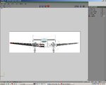
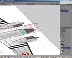
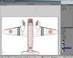
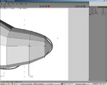
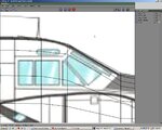
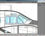
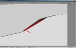
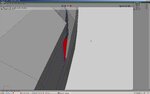
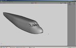
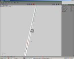
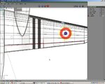
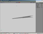
First step is to define the scale needed for the drawings. For this I create a simple box referred to as a “bounding box”. I do not use the actual “bounding box” function in Wings, because I like to move my templates around during the build process. I use the “image plane” function. Here we only really need one dimension (i.e. wingspan = 7’). When setting up the templates note that the Z axis in Wings is reversed from that of RealFlight (RF). This means that –Z will be the nose of the aircraft. Image 1
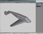
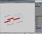
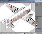
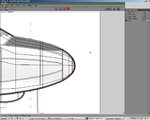
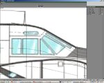
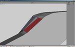
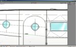
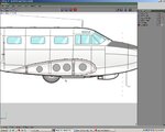
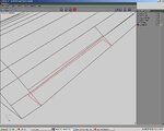
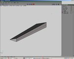
Then position and scale the side & front views to line up with the top view. With all images scaled and positioned, we’re ready to start modeling. Image 2
First step is to define the scale needed for the drawings. For this I create a simple box referred to as a “bounding box”. I do not use the actual “bounding box” function in Wings, because I like to move my templates around during the build process. I use the “image plane” function. Here we only really need one dimension (i.e. wingspan = 7’). When setting up the templates note that the Z axis in Wings is reversed from that of RealFlight (RF). This means that –Z will be the nose of the aircraft. Image 1
Then position and scale the side & front views to line up with the top view. With all images scaled and positioned, we’re ready to start modeling. Image 2
Attachments
Last edited:
dhk79
Well-known member
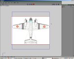
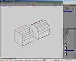
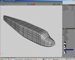
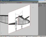
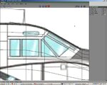
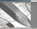
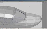
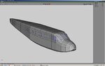
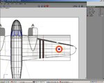
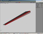
Examining the 3-view plus looking at some pictures, I pick primitive shapes that will make the final shaping go easier. In this case, the aft fuselage is very blocky so a cube will do well here. For the forward, the top is quite rounded but the bottom is still blocky so a half cube topped with a half cylinder will be my start. Initially scale the primitives to match the width of the center fuselage. Weld the two half primitives to get one new compound primitive for the nose. Position the two primitives before and after the windscreen. Image 3
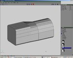
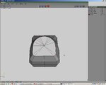
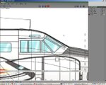
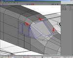
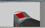
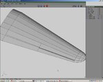
Now the top & bottom edges are rounded so bevel those lines a bit. Image 4
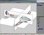
Add lines on the cube to match the number of vertices on the compound primitive and delete any lines that might be crossing the faces we’re going to join. I also added an extra pair of lines to both objects to aid in the shaping of the top surface of the fuselage. Image 5
Now the top & bottom edges are rounded so bevel those lines a bit. Image 4
Add lines on the cube to match the number of vertices on the compound primitive and delete any lines that might be crossing the faces we’re going to join. I also added an extra pair of lines to both objects to aid in the shaping of the top surface of the fuselage. Image 5
Attachments
dhk79
Well-known member
Attachments
Last edited:
dhk79
Well-known member
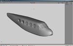
As long as you don't scale any current points, you can freely move lines along the Z axis and add cuts everyplace the fuselage shape changes. Panel lines are a good start, but look closely at both the top & side images for any that don’t have a panel line (plus many 3-views aren’t this nice). Don’t worry if the panels on the top & side images don’t line up exactly, they seldom do on drawings (unless they are very accurate design drawings). Image 8
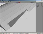
At each cut in the fuselage scale along the X axis from looking at the top and move & scale along the Y axis while looking from the side. The tail end is not visible from the top, so you have to guess from the others preceding it. Image 9
That completes the initial shaping of the fuselage. From this point, the final shaping of each section should be a lot easier than if you had started with just a cube or a cylinder.
Attachments
Last edited:
dhk79
Well-known member
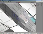
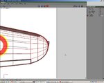
To start shaping the nose, connect all the nodes on the front face. Also add a line by cutting down the bottom. Image 10
Using the side view, move the center node out to the end of the fuselage. Image 11
Cut the extended lines to add additional nodes and scale uniformly (move along Y if needed) to create the rounded shape. Image 12
Do the same for the aft end.
Using the side view, move the center node out to the end of the fuselage. Image 11
Cut the extended lines to add additional nodes and scale uniformly (move along Y if needed) to create the rounded shape. Image 12
Do the same for the aft end.
Attachments
dhk79
Well-known member
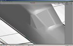
Move the front image along the Z axis to the thickest part of the fuselage. The image will be used as a general guide for the shape of each fuselage section. I say a guide because it will only match the tallest and widest sections (these are not necessarily the same section on all aircraft either). But together with the sections that get modified one at a time, it’ll be enough. Image 13
I like to shape just half of the fuselage to avoid making mistakes in always selecting pairs of nodes and then having to scale along the X axis, rather than just moving one node. So loop-cut the fuselage and discard half of it.
Now moving one or two nodes at a time adjust the section, then move the image back to the next section and do it again. With the prior preparation of the primitives, plus scaling in two dimensions, very few nodes will need to be moved on this fuselage (mostly just along the top edge).
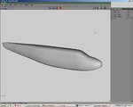
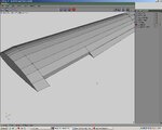
When done take a quick look in rendered view which will show you any discrepancies. Image 14
That completes the primary fuselage shaping, now on to the windows.
I like to shape just half of the fuselage to avoid making mistakes in always selecting pairs of nodes and then having to scale along the X axis, rather than just moving one node. So loop-cut the fuselage and discard half of it.
Now moving one or two nodes at a time adjust the section, then move the image back to the next section and do it again. With the prior preparation of the primitives, plus scaling in two dimensions, very few nodes will need to be moved on this fuselage (mostly just along the top edge).
When done take a quick look in rendered view which will show you any discrepancies. Image 14
That completes the primary fuselage shaping, now on to the windows.
Attachments
dhk79
Well-known member
Switch to wire-frame view of the fuselage and zoom in on the cockpit area looking through to the side image. Image 15
Here use the “connect” command located in the tools menu, rather than the connect pop-up menu. The connect command allows you to add nodes and lines connecting to any other nodes and lines. It even allows connection across multiple lines. This is good command to practice to see what it does, as it will come in extremely handy.
To use it click on a line and hold down the left mouse button and you will be able to move the newly created node along the line to get the placement exact. When you release the button the node becomes fixed, but you now have a line hooked to your cursor that you can connect to another line by the same process. The command will continue or chain until you press the right mouse button. Of course in this process if you select a node, it will not create a new node nor will you be able to move its position. Shifting the view by either pressing the center mouse button or using the X, Y, or Z (and the shifts) will not interrupt the command.
Image 16 shows a connect command going across the bottom edge of the window and adding nodes to three additional lines along the way.
You’ll also notice that at the front corner of the windshield there was not a line, so I just selected the next available line to put the new line down where I wanted. You can also add helper lines to enable getting the ones you really need.
Attachments
dhk79
Well-known member
Continue this process and outline both the panes and the frames, don’t worry about cleaning it up until the area is all mapped out. It should look something like Image 17. Actual extended lines may vary depending on what order you do them in.
This is an old plane built long before curved glass came into fashion, so now we have to make each pane flat. Start by deleting every line that crosses a pane (the lines in red are the ones I’m deleting). Finish the next couple of steps on the side first then you’ll have a better idea of what’s needed for the front. Image 18
Next on the three side panes, select each face (one at a time) and flatten normally. Then switch to line mode and make the edges hard. Image 19
Note that I’ve changed the display properties for the hard lines. The default color is green, but I find that blue is easier for me to see.
Attachments
dhk79
Well-known member
To do the center glass pane, the other half of it will be needed. Mirror the loop-cut face of the fuselage and this side will be duplicated to recreate a whole fuselage, complete with all the changes made so far. Then delete the line down the middle of the center pane and perform the same flatten/harden process to it. When done add the line down the middle again and reloop-cut the fuselage. Image 20
Looking at both the top & side views, try figure out if any lines need to be moved to go around the corner (I wasn’t 100% sure, but decided to leave it as it is and that way I could show how to fix it up after the fact). So again delete any lines crossing the two last panes. Image 21
Again the flatten/harden steps.
Attachments
dhk79
Well-known member
Looking over the initial results for the glass planes, you’ll see that there is some distortion on the model. This is not totally unexpected; in fact I’d be very surprised if there wasn’t any. Image 23 (for those counting, there's always at least one, there is no image 22 - I deleted it long ago)
At the end of the last step, the panes were all flattened. From this point on they will be manipulated only as flat objects. This means moving the panes as a whole, rotating around edges, or moving corners along edges. Starting with the pane in the front center, adjust to conform to the shape of the fuselage. Since this pane must keep its edge on the X axis, it may only be moved in the Y & Z directions or rotated around the X.
Looking at the pane from the cut edge: Image 24
The top edge looks like it’s in the right position, but the bottom needs to come out slightly so rotate clockwise around the top edge. This action requires the use of the advanced commands accessed by right clicking the menu options rather than left clicking them (note you have to have the advanced menu options enabled in Wings before you can use them).
Attachments
Last edited:
dhk79
Well-known member
With the pane highlighted, right click to bring up the menu, then right click on rotate. The mode selection options at the top of the window will change to just three selections – rotating a round an object does not make sense in a 3D world. Click on the line mode and select the top edge of the pane. The face remains highlighted in red, but a blue axis of rotation will appear. Image 25
Left click to execute the command and rotate the pane out to line up the lower edge.
On the next pane, move it to line up the bottom corner of the pane that was just positioned. Then move it just a bit aft. Image 26
Using the same procedure as used to rotate the center pane, rotate this one to first line up the side adjacent to the center pane by using the lower edge as an axis. Then rotate it slightly aft around the adjacent to center line. Image 27
Attachments
Last edited:
dhk79
Well-known member
Rotate the front side window in slightly to start the front curve of the windshield. Image 28
On the corner window start with the top edge and align it between the side and front panes. Rotate the pane down along the top edge to align the bottoms. Continue working back & forth between panes and adjusting the edges and corners until you get the panes lined up to form the windscreen. Image 29
Now clean up the corners around the panes. Delete extra lines, connect to corners of the panes, and add lines as needed to give the areas a smooth transitioned appearance. Image 30 & Image 31
Attachments
dhk79
Well-known member
To give the panes a more defined appearance, select each pane’s face and extrude inward .01 (hold ctrl-shift to do it by this increment). Be sure to mirror the fuselage before doing the center pane. Image 32
Re-cut the fuselage back in half and do the other side windows. For the round ones, bisect the windows first horizontally then vertically, make diamond shapes, and then cut the corners to make eight sided shapes. Delete any extra lines that are too close to others. Image 33
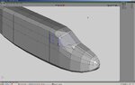
Mirror the fuselage half again and it’s completed. Wings reports the fuselage is roughly 600 polygons. Rule of thumb is to double that number to get an final estimate. Image 34 & Image 35
Re-cut the fuselage back in half and do the other side windows. For the round ones, bisect the windows first horizontally then vertically, make diamond shapes, and then cut the corners to make eight sided shapes. Delete any extra lines that are too close to others. Image 33
Mirror the fuselage half again and it’s completed. Wings reports the fuselage is roughly 600 polygons. Rule of thumb is to double that number to get an final estimate. Image 34 & Image 35
Attachments
dhk79
Well-known member
Start the wing with a cylinder, turn on its side, select the far end, and from the tools menu – center X. This moves the whole object such that the far side is on the centerline. This will provide a good mirror plane for when the finished wing is duplicated for the other side. Image 36
Scale the cylinder along Z and manipulate node pairs to match the wing shape. Add more nodes where needed to define the leading edge. Image 37
Switching to top view, move the top image down if needed to see the wing primitive. This is a very simply shaped wing, so just move the outside face to the end of the aileron. Make a cut across the wing. Image 38
Move the resulting line inward to the edge of the fuselage. This will prevent the part of the wing going through the fuselage from deforming when the outboard end is scaled.
Attachments
Last edited:
dhk79
Well-known member
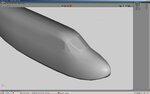
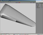
Select the outboard face and scale uniformly and move in the Z direction to shape the wing. With the face still selected extrude in the X direction a bit and again scale and move in the Z direction. Repeat this process several times to get the rounded shape of the wing tip. Image 40 (there is no Image 39)
It’s easier to make the cuts for the control surfaces while the wing is flat, so do that before setting the dihedral. Use the same connection technique used on the windows to outline the control surfaces. In wire frame, do the top outlines first doing the guide line between the flap and aileron first. Then do the front edges of the two control surfaces. Added lines are shown in red. Image 41
Switch to the bottom view and turn off the top image. With the wing in wire frame view, once you start a connect command sequence the nodes on the other side of the wing will become visible. This allows the node/line placement on this side to match the other.
Cutting the flap out first, highlight the boundary edges going (around the trailing edge) and make a loop-cut to separate the flap. Image 42
Attachments
Last edited:
dhk79
Well-known member
Turn off the display of the flap so that the wing trailing edge can be cleaned up. Switching out of wire frame you can see the deformation of the 3D model where the flap was. If this is not fixed it will cause problems when you go to UVW and texture map the part (if not worse). Image 43
Clean-up is easy, just go to node mode and connect the top & bottom nodes in each interior corner. The nodes for both corners are highlight here, but only do one at a time or you’ll get extra lines. Image 44
While here also connect the top & bottom nodes the aileron (in the right corner). This line will be needed to loop-cut the aileron, which is the next step.
Attachments
dhk79
Well-known member
With both flap & aileron cut out, hide the wing and display the two control surfaces. Again there is a 3D error because the corners aren’t defined, so connect the top & bottom nodes. Image 45
Just like on real R/C planes there are several ways to make hinges. I will show you the two I use most commonly. The first I use on scale aircraft, which is like a hidden hinge, where I do not want a hinge line to show when the control surface is not deflected. The second is for normal R/C type hinges, where you always see a beveled edge on the control surface.
Both types start with adding a line across the front of the control surface. Image 46
For a hidden hinge move this line forward to create roughly 45° bevels for the hinge. Image 47
For an R/C hinge (on the aileron), bevel the top & bottom edges for nearly the same effect. Image 48
Attachments

dhk79
Well-known member
To set the dihedral, switch to front view and combine the control surfaces and wing into one object. Select all nodes other than the center line and rotate around an axis (advanced command option) created by two nodes, one on the trailing edge and one on the leading edge (I had to add this one due to not having a line on the leading edge because I made it flat). Image 51
The process is identical for the stabilizers (except they are a uniform thickness, so only scale in the Z direction) and individual pictures aren’t included. Image 52
The process is identical for the stabilizers (except they are a uniform thickness, so only scale in the Z direction) and individual pictures aren’t included. Image 52