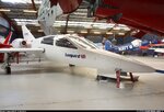
Leapard 4 - Build

dhk79

Well-known member
This is the Chichester Miles Leopard 4 biz-jet as requested by Norton. Mwilson914 has suggested a 1/5 scale, so I'm going to tackle this one a little differently. I've got the 3-views laid out at 1/5 scale and I'm going to grab my digital calipers and figure out what we'll be working with as an RC model, before I even get started with the 3D stuff.

Doug
 

Attachments

  • Image01.jpg
    Image01.jpg
    74.9 KB · Views: 28
At a 1/5 scale, this plane has a 56.4" wingspan, figuring composite construction I'd guess we're looking at about 12-20# (depending propulsion).

At this scale the engine pods are 3.35' at maximum diameter. A JetCat P20-SE is 2.4" in diameter and so will fit. two of those will put out 10.5# of thrust, so if I can keep the weight down and still use realistic weights for components this combo will work.

However, two of these puppies can suck 7oz of full per min at full power, so with a 40oz tank (3.25x8x4"), we'll only be looking at about an 8 min flight. I may be able to fit a 60oz tank (3.78x8.5x4.49") and keep the cockpit detail, but it could be close.

Checking into an electric option, the biggest EDF unit that will fit is 70mm (2.7"), but even with a super hot motor two of them will only pump out about 6# of thrust. So I don't figure an EDF is a viable solution for this plane.
 
Looking at all the pictures, I've taken a guess for the starting airfoils. The wing looks to be about a 12% thickness and semi-symmetrical with a low camber at the root. The images of the tip are too small to really tell, so I'll start with a fully symmetrical there, which will give the wing a little aerodynamic washout (even at zero incidence).

For the root a NACA 1412 (12% thick, 1% camber) and for the tip a NACA 0012 S (12% thick, 0 camber) look like good candidates, so I will model with those.
 
Basic wing shape is roughed out, using the airfoils noted above.
 

Attachments

  • Image02.jpg
    Image02.jpg
    78.5 KB · Views: 22
I dearly love 3-views created by graphic artists and not engineers or draftsmen. Notice that the gear is in the correct position and is the correct scale according to the drawings, yet when retracted it will not fit within the wing and extends into the aileron.

Looks like I get to become creative.
 

Attachments

  • Image03.jpg
    Image03.jpg
    36.6 KB · Views: 7
  • Image04.jpg
    Image04.jpg
    41.2 KB · Views: 7
  • Image05.jpg
    Image05.jpg
    56.5 KB · Views: 12
The actual photos seem to show that the gear is significantly closer to the leading edge than is shown in the 3-Views.
 

Attachments

  • 0722920.jpg
    0722920.jpg
    331.1 KB · Views: 26
Misinterpreted

i think that the gear folds up so that it runs parallel with the wing, not at 90 degrees like you had it. if that makes any sense, let me know if you need me to better explain what i mean.

sometimes orthographic projections can be confusing.
 
Don't think that's the case with the gear doors the way they are (hinged straight, parallel to the fuselage), and orthographic projections are not confusing to someone who has used them professionally for over 30 years. These are simply wrong.
 
I would be glad to help ya out if I could. Just let me know. I'm off to work now but will be back on sometime soon to check the forums.
 
Nah, not at his expense. Just in his thread! (Of course the really funny stuff seems to be underground, no?)
 
Back
Top