Avro Anson MK1 WIP

herc40

New member
Hello,
I liked doing the Deuces Wild twin engine aircraft, so much, that I decided to do another Twin engine effort. This is the Avro Anson Mk1, the Anson was the RAAF's first retractable undercarriage, low wing monoplane, and served in great numbers (1,028 aircraft) following 1935 orders, when the RAAF set out to modernise its equipment.

This will be an undertaking, that may last a long time, but I think it will be good in the end
 

Attachments

  • Avro Anson MK1.jpg
    Avro Anson MK1.jpg
    31.7 KB · Views: 24
  • Avro Anson MK1 2.JPG
    Avro Anson MK1 2.JPG
    30.1 KB · Views: 15
  • Avro Anson MK1 3.JPG
    Avro Anson MK1 3.JPG
    16.7 KB · Views: 11
  • ca4119_boxart.jpg
    ca4119_boxart.jpg
    18.8 KB · Views: 33
  • ca4118boxart_1.jpg
    ca4118boxart_1.jpg
    34.1 KB · Views: 46
Last edited:
uhhh... from my experience with the avenger... save LOTS of polys for the turret. That rounded surface is hard to make look good without them. I look forward to this. Can I request models of scale engines rather than models of the full-size? :eek:
Looks great so far. Lots of glass... should be pretty.
 
Hey

I think I'm gonna try to POLY MAX this baby out. With a full cockpit, glass, and the works. The landing gear alone will eat up a few, I found a nice pic of how it is supose to pivot. I think it will be a long time to make it but thats the fun. Here is some pics of the landing gear.
 

Attachments

  • wheels.jpg
    wheels.jpg
    50 KB · Views: 16
  • wheel working.jpg
    wheel working.jpg
    78.8 KB · Views: 19
  • Avro Anson MK1 4.JPG
    Avro Anson MK1 4.JPG
    37 KB · Views: 10
Last edited:
Little more progress

Here is a pic of some work I did today.
 

Attachments

  • Avro Anson MK1 5.JPG
    Avro Anson MK1 5.JPG
    38.9 KB · Views: 8
  • Avro Anson MK1 6.JPG
    Avro Anson MK1 6.JPG
    35.3 KB · Views: 7
  • Avro AnsonMK1 7.jpg
    Avro AnsonMK1 7.jpg
    30.4 KB · Views: 15
Last edited:
hello

worked on the cockpit area today, a whole lot of glass, but its looking good. Here is a pic.
 

Attachments

  • Avro Anson MK1 8.JPG
    Avro Anson MK1 8.JPG
    30.9 KB · Views: 39
Hey herc, its looking good! I just read an article in Aviation History magazine about the 10 best emergency landings. Here's a quote from one:
"Royal Australian Air Force Leading Aircraftman Leonard Fuller was slowly descending to cruise at a lower altitude in his Anson Mk. I when he pancaked onto the Mk. I of LAC Jack Hewson, who had been flying level, unseen directly below him. The mating was facilitated by the fact that Ansons had clumsy, hand-cranked retractable landing gear that took a numbing 140 turns to raise and another 140 to extend for landing. So if they weren’t in a hurry, Anson pilots like Fuller often simply left the gear down and accepted the 30-mph speed penalty. This meant that Fuller’s airplane essentially straddled Hewson’s, its wheels sitting atop Hewson’s wings."
It was a great article and the entire magazine was great http://www.historynet.com/the-10-greatest-emergency-landings.htm scroll down and it's on page 3. Its also interesting how they would leave the gear down but the quote seems to back up their actions. The landing gear seems to act like a DC-3. Like most of your models, I'm guessing it will be converted to G3.5...please. Best of luck!
 
Last edited:
Here ya Go

Here ya go buddy, I don't know what your looking for, in detail, so I just made 2 pics. If you don't see what you want to see, let me know.


Vonfife911, I will give the file to my long time collaborator, Flexible, and He will take it into G3.5. I hope it will be as popular as some of my other work.
 

Attachments

  • Avro Anson MK1 9.JPG
    Avro Anson MK1 9.JPG
    95.4 KB · Views: 30
  • Avro Anson MK1 10.JPG
    Avro Anson MK1 10.JPG
    85.8 KB · Views: 33
Last edited:
Well, I just wanted to see what you were doing for the turret (#1) in terms of poly count. Looks like you've done what I did and started with a sphere primitive. You'll probably need more polys for that by the time you get all the spars for the windows sorted out. I also wanted to see a few rough spots (#2) where there looked like some "stretching" was going on. No hard lines yet? Also noticed that you like to leave the control surfaces like a piece of flat balsa. Any reason for that? If that is your intent I would try to bevel those edges. I personally would never leave an edge looking as sharp as that. I know this project is still young but I am just watching closely. ;) Really a nice subject to do a lot of really neat things.
 
yes it is.......

still young in the making, and it will take some time to do. I am taking my time, working on one section at a time. I just made a basic shape and then I'm fine tuning the pieces. I will get it right at the end.

I worked a little bit on the Fuse today, and made the roundness on top. here are some pics.
 

Attachments

  • Avro Anson MK1 11.JPG
    Avro Anson MK1 11.JPG
    38 KB · Views: 23
  • Avro Anson MK1 12.JPG
    Avro Anson MK1 12.JPG
    34.1 KB · Views: 19
  • Avro Anson MK1 13.JPG
    Avro Anson MK1 13.JPG
    20.4 KB · Views: 12
Last edited:
Modelling a fuselage wing connection

Hello herc40,

small tip:

I noticed that you don't connect the wings to the fuselage. I know this is often complicated, especially when the wings are going wide at their root and often flowing into the fuselage. Here's a small modelling tip:

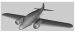
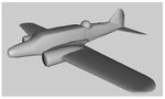
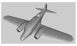
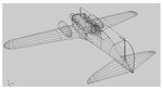
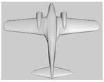
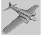
First: (As you already have) Model the wings and the fuselage as seperate objects (First Screenshot).

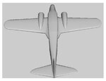
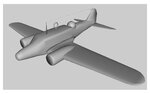
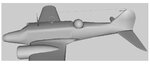
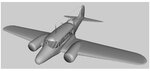
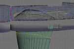
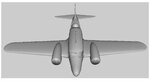
Second: Knife the ending of the wings out of the fuselage by using the blueprints for orientation. (Second Screenshot)

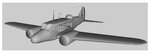
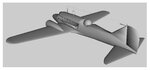
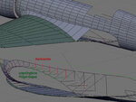
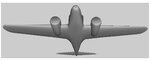
Third: Join the both objects and recreate the faces between the different parts. This will look a little bit strange at the beginning, but can be fixed via step four. (Third Screenshot)

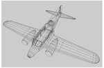
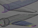
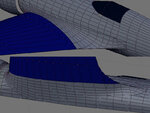
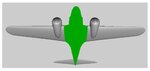
Four: Make a multi-cut on the new created faces and rearrange the vertices, so they are matching the flow into the fuselage (probably the most difficult part; Fourth Screenshot).

Because you want to stay low-poly, here's my way to do it:

Don't model the the wings as seperate objects. Knife the root of the wings out of the fuselage and extrude directly out of the fuselage to the real starting point of the wings (the point where they will brake away). Then extrude from there to the tip of the wings and refine the object.

If I have a wing profile on the blueprints I simply make a vertex loop following the profile, extruding it to a small wing part and then apply a boolean modifier between the fuselage and this wing dummy, to get the starting cuts on the fuselage. Going this way you have a better control about the poly density of the wings and that you are not carry around to much needless edge lines on the wing tips, because the knife on the fuselage sometimes leading to more vertices to extrude than necessary to get the wing shape right.

If you don't model a wing fuselage connection, you will never see a nice hard line, and how the wings are ending on the fuselage. It's also important for UV-Mapping, because you preventing uneccessary texturing of faces nobody can see.

BTW: I have to fight with this problematic on your citation too.

Max
 

Attachments

  • H1-tut1.jpg
    H1-tut1.jpg
    179.7 KB · Views: 20
  • H1-tut2.jpg
    H1-tut2.jpg
    59.5 KB · Views: 15
  • H1-tut3.jpg
    H1-tut3.jpg
    115.4 KB · Views: 24
  • H1-tut4.jpg
    H1-tut4.jpg
    117.1 KB · Views: 21
Last edited:
In wings3d nomenclature:

Trace the root airfoil into the side of the fuselage. Loop cut that away. Extrude the airfoil away from the fuselage. Align those verticies along the y-axis. Extrude to the full length of the wing then shape the root of the wing by adjusting the verticies. Shape the tip as you normally would...

As you've already made the wing you could just loop cut the wings close to the fuselage and trace the airfoil on the fuselage and loop cut. Then verify you have the same number of verticies on the fuselage and wing root.... then bridge them and blend the verticies as max instructed.

This is what I did with the bearcat. It turned out great but was a bit more work than the average wing and fuse separation. Blending looked better and I never made that connection until now. Probably will from now on.
 
I agree with Max 100%. That's what I've done on several models. (extrude them out from the fuse) One example of this is my P-47 wing / wing fillets. This is the only way to go in order to achieve the best possible look and fit.

Looks like a nice H-1 you're working on Max?
 
Looks like a nice H-1 you're working on Max?

I'm not working on a H-1 :) The pictures are out of a blender forum I'm reading regulary. Long time ago there was this H-1 project somebody made and he described how he was modelling the connection between fuselage and wings. I remembered the description and especially the fitting screenshots he had attached to his post, when I saw the pictures from herc40. As you can see the aircraft has already a very high poly count at an early modelling stage -> so nothing for Realflight, more for rendering and animation....

Max
 
Thanks Guys

I think this the way to go too, just couldn't figure out how to make it look better, but this may work. I will try to get this working for me, and have some shots soon.
 
Here is one fillet

Is this what you were saying guys? As you can see this is the underside, and the Right wing meets the fuse pretty good. I need to smooth some of the areas out, but thanks for the idea.

Here is one with the top side showing.
 

Attachments

  • Avro Anson MK1 14.JPG
    Avro Anson MK1 14.JPG
    32.7 KB · Views: 23
  • Avro Anson MK1 15.JPG
    Avro Anson MK1 15.JPG
    38.1 KB · Views: 25
Last edited:
looks much better. do you have hard lines on the joint where the wing butts to the fuse part? Thats usually what to do when that shading thing goes on in Wings. Just highlight the edges... right-click hard lines. That or select the face of the wing root then go to edge view then make hard lines. make sure you do all your wing and control surface trailing edges too... just cleans things up a lot.
 
ok

will do, Willsonman.


EDIT: ok I added the hard lines and finished the filet for the left wing. I also made the windows in the nose section. checkout the pics.
 

Attachments

  • Avro Anson MK1 17.JPG
    Avro Anson MK1 17.JPG
    31.4 KB · Views: 19
  • Avro Anson MK1 16.JPG
    Avro Anson MK1 16.JPG
    24.7 KB · Views: 14
  • Avro Anson MK1 18.JPG
    Avro Anson MK1 18.JPG
    26.2 KB · Views: 17
Last edited:
Back
Top