
You are using an out of date browser. It may not display this or other websites correctly.
You should upgrade or use an alternative browser.
You should upgrade or use an alternative browser.
Big Red
- Thread starter technoid
- Start date
technoid
Well-known member
It doesn't seem like it but you start this model 10 months ago
Wow.. I didn't look but it seems even longer to me. Maybe a miracle will happen and I'll finish it this time.
technoid
Well-known member
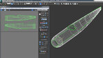
Okay guys true to her name Big Red has become a really big plane. I upped the Wingspan from 96 inches to 144 inches and just finished the new physics. She needs some breathing room so I've been flying her from the Sod Farm Airport and she fly's and looks great. I'm going to take a little break and then start the mapping process. Here's a couple pictures from the RF editor showing the new Landing Gear and Guy Wires.
Attachments


TPRogers
Member
Okay guys true to her name Big Red has become a really big plane. I upped the Wingspan from 96 inches to 144 inches and just finished the new physics. She needs some breathing room so I've been flying her from the Sod Farm Airport and she fly's and looks great. I'm going to take a little break and then start the mapping process. Here's a couple pictures from the RF editor showing the new Landing Gear and Guy Wires.
technoid!
Yet ANOTHER beauty! LOVE the size too! I have to mention that I like the larger models as that's what I fly in actual RC.. so .. yeah, gonna like this! Being the WWI Fan that I am, I noticed that if I squint my eyes, it kinda looks like a Fokker!
TPRogers
technoid
Well-known member
technoid!
Yet ANOTHER beauty! LOVE the size too! I have to mention that I like the larger models as that's what I fly in actual RC.. so .. yeah, gonna like this! Being the WWI Fan that I am, I noticed that if I squint my eyes, it kinda looks like a Fokker!
TPRogers
Thanks... yeah she's a big one for sure. Usually my largest planes are 120 I don't know why this one got so big!
uncle twist
Well-known member
I`m not even going to go there.Thanks... yeah she's a big one for sure. Usually my largest planes are 120 I don't know why this one got so big!
technoid
Well-known member
Finally a bit more progress to report. I've been doing some painting on the house so modeling has slowed down, and when I'm not painting I'm to tired to work on it. Yeah I'm an old guy. But I finally had some time so I did a few things. (The plane names below are working names I'm not sure what the final names will be)
1. I resized the Giant Bipe (144 inch) to the Radial Bipe size (96 inch) and reworked the Radial Bipe physics for the slight difference in size from the original plane. What I'm planning to do is after I map the Giant Bipe I'll resize it again to the Radial Bipe size (96) and the mapping should follow the resize so I can release both planes, the 144 inch and 96 inch. I'm thinking there's a lot more people interested in the 96 inch wingspan, and it does have snappier handling so it's more fun to fly. I wanted the Giant Bipe because sometimes I like to fly slow and graceful but after I finished the Giant Bipe it looked so nice I wanted something snappier to fly too. So that's the plan, release both at the same time with something like Big Red Mk I and Big Red Mk II. But if you have some thoughts on the naming scheme share it with me.
2. When getting ready to map I found out the fuselage wasn't split down the center so I had to go back and fix that, which made me run out of resources again so I had to go back and find something to modify to get a few more triangles. I hope RF 8 brings a larger poly count because using the engines I create eats up a lot of resources before I even start. If we could get a 40 or 50k poly limit that would really help.
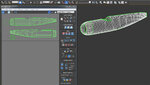
3. After all that I was finally ready to start mapping so I did a little work and finished the fuselage and will put a picture below of what I did. There's not much mapped but it was a lot of work getting there.
1. I resized the Giant Bipe (144 inch) to the Radial Bipe size (96 inch) and reworked the Radial Bipe physics for the slight difference in size from the original plane. What I'm planning to do is after I map the Giant Bipe I'll resize it again to the Radial Bipe size (96) and the mapping should follow the resize so I can release both planes, the 144 inch and 96 inch. I'm thinking there's a lot more people interested in the 96 inch wingspan, and it does have snappier handling so it's more fun to fly. I wanted the Giant Bipe because sometimes I like to fly slow and graceful but after I finished the Giant Bipe it looked so nice I wanted something snappier to fly too. So that's the plan, release both at the same time with something like Big Red Mk I and Big Red Mk II. But if you have some thoughts on the naming scheme share it with me.
2. When getting ready to map I found out the fuselage wasn't split down the center so I had to go back and fix that, which made me run out of resources again so I had to go back and find something to modify to get a few more triangles. I hope RF 8 brings a larger poly count because using the engines I create eats up a lot of resources before I even start. If we could get a 40 or 50k poly limit that would really help.
3. After all that I was finally ready to start mapping so I did a little work and finished the fuselage and will put a picture below of what I did. There's not much mapped but it was a lot of work getting there.
Attachments

TPRogers
Member
Finally a bit more progress to report. I've been doing some painting on the house so modeling has slowed down, and when I'm not painting I'm to tired to work on it. Yeah I'm an old guy. But I finally had some time so I did a few things. (The plane names below are working names I'm not sure what the final names will be)
1. I resized the Giant Bipe (144 inch) to the Radial Bipe size (96 inch) and reworked the Radial Bipe physics for the slight difference in size from the original plane. What I'm planning to do is after I map the Giant Bipe I'll resize it again to the Radial Bipe size (96) and the mapping should follow the resize so I can release both planes, the 144 inch and 96 inch. I'm thinking there's a lot more people interested in the 96 inch wingspan, and it does have snappier handling so it's more fun to fly. I wanted the Giant Bipe because sometimes I like to fly slow and graceful but after I finished the Giant Bipe it looked so nice I wanted something snappier to fly too. So that's the plan, release both at the same time with something like Big Red Mk I and Big Red Mk II. But if you have some thoughts on the naming scheme share it with me.
2. When getting ready to map I found out the fuselage wasn't split down the center so I had to go back and fix that, which made me run out of resources again so I had to go back and find something to modify to get a few more triangles. I hope RF 8 brings a larger poly count because using the engines I create eats up a lot of resources before I even start. If we could get a 40 or 50k poly limit that would really help.
3. After all that I was finally ready to start mapping so I did a little work and finished the fuselage and will put a picture below of what I did. There's not much mapped but it was a lot of work getting there.
Man but this process is FASCINATING! I tip my cap to you technoid and everyone else that can model using this medium! THANKS to csgill75, I now have a bead on the editor, but to actual model a plane from jump... just blows me away! I'm finishing my 2nd Fokker DVIII in 1/4 scale for RC... but that's wood ... metal ... and fabric. The process here is completely alien to me... but it's GREAT!
TPRogers
technoid
Well-known member
After looking at the fuselage mapping I don't think it will work properly since the vertical edges of the fuselage are bowed in the map, so anything straight you put in the color scheme will get bent when it's applied to the plane surface in 3d. So I went back and mapped it different by separating the front of the fuelage where it's rounded off to it's own part. Since this is the first time I've ran into this maybe abraser or Fly_electric can chime in and say which way I should go. Here's a picture of both ways and they're separate files so I can easily use either one at this point. So if either of you see this post please chime in with your thoughts. Thanks!
Attachments
uncle twist
Well-known member
Hey Technoid, I`m not Abaser or FE.After looking at the fuselage mapping I don't think it will work properly since the vertical edges of the fuselage are bowed in the map, so anything straight you put in the color scheme will get bent when it's applied to the plane surface in 3d. So I went back and mapped it different by separating the front of the fuelage where it's rounded off to it's own part. Since this is the first time I've ran into this maybe abraser or Fly_electric can chime in and say which way I should go. Here's a picture of both ways and they're separate files so I can easily use either one at this point. So if either of you see this post please chime in with your thoughts. Thanks!
, but I`ve done a fair amount of CS`s. I`m sure you`re aware that if it`s a solid CS being applied, either way will work just fine. I would go with your second version however, just in case someone wants to add some graphics. Another option, is to map it from the front view. either way has its advantages and disadvantages depending on the CS / graphics being applied. I think most I`ve done were from a side view though. know matter, compound curved surfaces have always been a bit of a challenge for anyone doing CS`s.
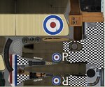
You may want to take a look at the .TGA / map of the Sopwith CS I did (B/W checkered front) it came out real nice IMHO. It might give you a better idea of what to do.
uncle twist
Well-known member
technoid
Well-known member
I`m bored, got it for ya, this is the other option, linear, this is only a partial of the .TGA, but gives you all the nose and fuse. You can see how much of a challenge I had. This is from the RF sopwith BTW.
Thanks I appreciate the info. Yes I knew solid was fine but I was thinking about a vertical line, like a stripe or some sort of graphic.
Last edited:
uncle twist
Well-known member
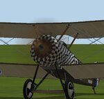
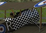
If that`s your concern, then you should try to lay it out flat, like the Sopwith example. That would give anyone wanting to do a CS with graphics the best palette to work with. There was very little, if any, stretching that I had to deal with. here`s a couple pics. of the finished plane. All things considered, the radius of the cowl front came out pretty nice.
Attachments
Last edited:
technoid
Well-known member
If that`s your concern, then you should try to lay it out flat, like the Sopwith example. That would give anyone wanting to do a CS with graphics the best palette to work with. There was very little, if any, stretching that I had to deal with. here`s a couple pics. of the finished plane. All things considered, the radius of the cowl front came out pretty nice.
Yes, that's why the second layout is better. A straight line will be straight.
doug schluter
Well-known member
nice CS uncle twist , the second layout looks like the one to go with alright technoid
uncle twist
Well-known member
Thanks Doug, I know you`ve DL`d it buy now..nice CS uncle twist , the second layout looks like the one to go with alright technoid
. Technoid, if all your concerned about is a vertical line/stripe around the cowl, then your second layout will work just fine. been there, done that..doug schluter
Well-known member
yes i have i think i have most of your CS's if not all of them
abaser
Well-known member
Tech, first of all, how are you mapping it in the first pic with the curved edges? Are you putting the fuselage at an angle? (sorry if I missed that explanation somewhere) I personally like to try to keep things like that all one piece. It prevents the two parts from accidentally getting scaled differently, and just makes doing the CS much easier especially if you have curved lines, checkers, or whatever. Anyway, I'm a little confused with the curved vertical edges. Looking directly from the side, they should be straight vertical on that plane.
Now, to prevent distortion on curved areas like the nose of your plane, it's really a rather simple task.....time consuming, but simple. All you have to do is manually arrange the verts in a straight or vertical line. For example, highlight all of the top row of verts on the map (on the curved areas only) that make up the center line. In the map editor window, there is a tool at the top of the toolbox that will allow you to arrange horizontally (or vertically if doing a vertical set). Click this and it will flatten the row. Now line them up with the existing top verts. I always like to use my multi colored chart for this procedure, but scaling the parts up real big and using the default checkerboard will work just as well.
Now, to prevent distortion on curved areas like the nose of your plane, it's really a rather simple task.....time consuming, but simple. All you have to do is manually arrange the verts in a straight or vertical line. For example, highlight all of the top row of verts on the map (on the curved areas only) that make up the center line. In the map editor window, there is a tool at the top of the toolbox that will allow you to arrange horizontally (or vertically if doing a vertical set). Click this and it will flatten the row. Now line them up with the existing top verts. I always like to use my multi colored chart for this procedure, but scaling the parts up real big and using the default checkerboard will work just as well.