
You are using an out of date browser. It may not display this or other websites correctly.
You should upgrade or use an alternative browser.
You should upgrade or use an alternative browser.
Newvie requesting help
- Thread starter richrfl
- Start date
technoid
Well-known member
Techniod, by no means I feel frustrated. I take interests in all responses, because I don't know what am I missing or someone else is assuming I know. Will check if I can find the video you refereced to. It would save some time.
As just FYI, the recently version of Blender, seems that solved some issues related to the pivots. (see my response to Donamy)
You may have seen that video already it was the one in the reply from asj5547 early in this thread. I built my first plane from that video and released it. (Boxie Flyer on the Swap Pages)
Here's a link to the post that has a link to that video
https://forums.realflight.com/showpost.php?p=298124&postcount=2
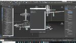
I imported your PC-21 file into Max, most of the pivot settings were good, but no NUP values were set for gears or gear doors.
Here are a few screenshots NUP settings, note left gear and left doors use a minus value.
Then I exported your model from Max and named the FBX as PC-21, dropped that in a folder of the same name and also placed your pc-21 v2 (TGA) in the folder, then I imported your model into RF9 with no problems.
Attachments

technoid
Well-known member
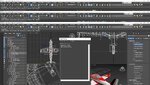
I guess I don't understand what I'm seeing here because I see lots of bad pivot points unless you only look at the control surfaces. Maybe something happens when I set it up in 3ds Max but here's what I'm seeing here.
Also maybe I'm doing it wrong but for parts like the fuselage, wings, stabilizers I center the pivot point on the part and then hit the transform button to set the correct pivot point direction.
Here's the pivot point issues I see here.
1. The fuselage pivot point is not centered on the fuselage and is the wrong direction.
2. Both wing pivot points are over the left wing and are pointed the wrong direction and are not set to the angle of dihedral.
3. Both horizontal stabilizer pivot points are centered on the fuselage and are pointed the wrong direction.
4. The vertical stabilizer pivot point is not centered on the stabilizer and is the wrong direction.
5. The spinner pivot point is at a small angle and not centered on the spinner.
6. Both cockpit pivot points are not centered on the cockpit part and are the wrong direction.
7. The right tire pivot point is not centered on the tire.
8. The wing gear door pivot points are not set to the dihedral angle of the wings.
9. The nose gear door pivot points are way back towards the end of the fuselage and are not centered on the gear doors.
I guess I don't understand what I'm seeing here because I see lots of bad pivot points unless you only look at the control surfaces. Maybe something happens when I set it up in 3ds Max but here's what I'm seeing here.
Also maybe I'm doing it wrong but for parts like the fuselage, wings, stabilizers I center the pivot point on the part and then hit the transform button to set the correct pivot point direction.
Here's the pivot point issues I see here.
1. The fuselage pivot point is not centered on the fuselage and is the wrong direction.
2. Both wing pivot points are over the left wing and are pointed the wrong direction and are not set to the angle of dihedral.
3. Both horizontal stabilizer pivot points are centered on the fuselage and are pointed the wrong direction.
4. The vertical stabilizer pivot point is not centered on the stabilizer and is the wrong direction.
5. The spinner pivot point is at a small angle and not centered on the spinner.
6. Both cockpit pivot points are not centered on the cockpit part and are the wrong direction.
7. The right tire pivot point is not centered on the tire.
8. The wing gear door pivot points are not set to the dihedral angle of the wings.
9. The nose gear door pivot points are way back towards the end of the fuselage and are not centered on the gear doors.
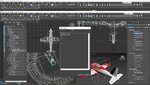
Yes, I only did a quick check of control surface pivots just to help him get his first model into Realflight, this model has many problems (nose gear doors only show from one side, transparent viewed from the other side) maybe the same mistake I made (one poly thick) spinner only shows half, right tire acts like a square wheel at slow speeds, Technoid noted the tire to rim off centre, and quite a few objects do not line up perfectly, but I remember how impatient I was to actually see that first model fly, so I think this is a live and learn project.
https://youtu.be/oRezyCt533E
Attachments


technoid
Well-known member
Well, guys, you are way ahead, no doubt. I think I am learning something here, like that of the fuselage pivot point.
I will slowly and carefully review all the pivot point issues, as well as the screenshots and files, and make due notes of my mistakes.
Thanks a lot!
Well let me tell you something.. if this is your first plane you've done a super job and all the issues you're seeing we all had to go through and get help with. So keep going you're doing great.
Well let me tell you something.. if this is your first plane you've done a super job and all the issues you're seeing we all had to go through and get help with. So keep going you're doing great.
Technoid, this is not only my first plane for RF but also the first time I use Blender, I have been doing some basic CAD design many times before, but much simpler than a model for RF. All I achieved is thanks to people like you that have been kind and patient to help a guy that has very little idea of what he got into.
technoid
Well-known member
Technoid, this is not only my first plane for RF but also the first time I use Blender, I have been doing some basic CAD design many times before, but much simpler than a model for RF. All I achieved is thanks to people like you that have been kind and patient to help a guy that has very little idea of what he got into.
Well keep going you're doing great.
Well, guys, you are way ahead, no doubt. I think I am learning something here, like that of the fuselage pivot point.
I will slowly and carefully review all the pivot point issues, as well as the screenshots and files, and make due notes of my mistakes.
Thanks a lot!
Check your P.M.
Here is the export EA from RF8 of Richfl's PC-21, richfl has some problems importing this into RF8 on his computer, can anyone try this to see if it loads okay in RF.
This is Richfl's very first model, so it has a few concerns (like nose gear doors transparent from inside view) but is a great attempt, I can see he will become a very good modeller.
This is Richfl's very first model, so it has a few concerns (like nose gear doors transparent from inside view) but is a great attempt, I can see he will become a very good modeller.
Last edited:
technoid
Well-known member
I haven't tried importing the EA yet but the reason the gear doors are transparent is they're flat, no thickness. So you'd need to apply a material named SBS (show both sides) to the doors to get them to look normal. Flat polys are normally only visible on 1 side so if you look at the gear door from the side you should see it, but from an angle you'll be looking through the transparent side a lot of the time.
Could be any of those causing the see through concern, or one poly thick doors, the very mistake I made with my first model, quick fix was to extrude the doors, double poly thick. Technoid's tip.
Just want to help Richfl import his work into RF, there is nothing like flying your own design, it motivates you to continue on.
Just want to help Richfl import his work into RF, there is nothing like flying your own design, it motivates you to continue on.
technoid
Well-known member
Could be any of those causing the see through concern, or one poly thick doors, the very mistake I made with my first model, quick fix was to extrude the doors, double poly thick. Technoid's tip.
Just want to help Richfl import his work into RF, there is nothing like flying your own design, it motivates you to continue on.
Yes they're one poly thick (what i called flat) but if the material applied to them is named SBS RealFlight will show both sides, of course what's on the outside of the door will be on the inside too so you can't paint each side separately you just see the same color on both sides.
In 3ds Max I'll apply a SHELL modifier and then you can set the Outside And Inside thickness. So I set the outside to zero and make the inside as thick as I want the door. Then covert the shell to an edit poly and you have what you want, a door with some thickness.
Great information Technoid, I know how to shell extrude in Wing3d but struggle a lot in 3DS Max, that piece of knowledge you shared will be very helpful.
Question, have you tried to import the PC-21 into RF9, all I need to know is that the EA file works.