RAF FE2b

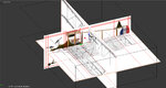
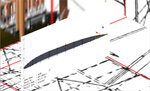
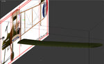
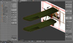
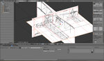
I've been trying to setup the 3 views for this. The problem is, they simply are not correct and do not match (they are not self consistent). It is like when they did the 3 view from the side, it was not done with an orthographic projection. From the top view, you can see the wing should be flat across the back. With the side view, you can see the wing looks like it sweeps back even with the prop. I know from photos of the reproduction that this is incorrect. The wing does not sweep back.

So I'm trying to decide whether to proceed, or move on to something else until I get something that is more consistent.
 

Attachments

  • Fe2b3View.jpg
    Fe2b3View.jpg
    277.7 KB · Views: 12
OK. I think I get the message. Quit whining! :)

It isn't like the finished product gets compared to the 3 view anyway. If it looks good, it is good.
 
Ratter,
The best way to deal with poor 3-views is to get some pictures of the aircraft and then try to figure out whether the top or side view is most consistent. Use the pictures to scale that one view along a single axis if needed. The one view is now the reference and the other views are scaled to it.

Then when the different views show something in different places, split the difference or use photos to figure out which is right.

As Jeff alluded most 3-views are usually off to some degree and would never pass an engineer's standard for accuracy. There are exceptions, however, and once I modeled an aircraft not because I liked it but because I found an absolutely perfect set of 3-views. I had to do that aircraft for the simple joy of working with drawings that were done by someone who knew what a scale was.
Doug
 
In this case, I think the side view is most suspect. I have an alternate side view that looks like it is at least orthographic, and may be more correct in general. So I'll give that other side view a try.
 
I've sometimes used more than one set of three views on a model and turned them on and off depending on which was less messed up.
 
Off for the weekend :). I have now put in the guide lines on the other side view and inserted it for use in blender. This side view works much better. There are still some minor issues, but that is what they are, minor.
 

Attachments

  • Fe2bBetter3view.jpg
    Fe2bBetter3view.jpg
    157 KB · Views: 14
I defined a single rib tonight. It takes 64 rectangular faces. I'm not sure I can afford the count since just the top wing alone has roughly 40 ribs. And then you need to connect them together. I could just extrude the whole thing, but then I need to do the wing ribs with bump maps. I would rather do something like Andy's technique. Ah well. I'm going to sleep on it before I decide anything.
 

Attachments

  • WingAirfoil.jpg
    WingAirfoil.jpg
    117.8 KB · Views: 7
If you want to use my method, create the whole wing. No need to create each individual rib at the moment. Granted, you will use way more polys than if you bumped it, but if you would like some help, let me know. Ill also look at your file if you want to send it. Just let me know and Ill PM you my email addy.
 
FYI, RF doesn't have an RAF 14 in its airfoil database. It does have a RAF 15. If you can find the rest of the specs (or data points) for the RAF 14, I'll see if I can find a closer match.
 
If you want to use my method, create the whole wing. No need to create each individual rib at the moment. Granted, you will use way more polys than if you bumped it, but if you would like some help, let me know. Ill also look at your file if you want to send it. Just let me know and Ill PM you my email addy.

No need yet but thanks for the offer. :)
 
FYI, RF doesn't have an RAF 14 in its airfoil database. It does have a RAF 15. If you can find the rest of the specs (or data points) for the RAF 14, I'll see if I can find a closer match.

The Raf 15 is a pretty close match.

The coordinates for the RAF 14 are:

http://www.ds-cats.com/~kurisawa/aeronautics/Airfoils/OpenFiles.link/A2051/OO0153_A.txt

and the graphic of the shape:

http://www.ds-cats.com/~kurisawa/aeronautics/Airfoils/OpenFiles.link/A2051/OS0153_A.png

and for the RAF 15:

http://www.ds-cats.com/~kurisawa/aeronautics/Airfoils/OpenFiles.link/A2050/OO0003_A.txt

and the graphic of the shape:

http://www.ds-cats.com/~kurisawa/aeronautics/Airfoils/OpenFiles.link/A2050/OS0003_A.png
 
Last edited:
I know this doesn't look like much progress, but I have created the lower left wing. I was having some problems getting this to be smooth. When I would smooth, the coloring of the wing tip got much worse. It turned out I needed to redo some of the normals. Anyway, I think I now have it. Also, although it isn't obvious, the ailerons are actually ready to cut out. I have edges where I need them for that.
 

Attachments

  • FE2bLowerWing.jpg
    FE2bLowerWing.jpg
    142.1 KB · Views: 10
Here is the latest. I now have both the upper and lower wing done, with the ailerons cut out. Progress continues to be slow, both because I need to learn to do things that were irrelevant with the flat foam planes I have done before, and because I am currently building a real Telink 44" Edge 540. I kind of sneak some modeling in, when I'm waiting for glue to dry on the Telink.
 

Attachments

  • FE2bWingsAilerons.jpg
    FE2bWingsAilerons.jpg
    243 KB · Views: 13
I'm not sure how blender does edge specification but in wings it is referred to as hard and soft edges. In Max its called crease. You may want to look into it to help resolve the irregular shading you are seeing especially around the ailerons and wing trailing edge. Looking great though!
 
The word, in Blender, you are looking for is sharp.;)

MR, if you get stuck on something, give me a shout.
 
I'm not sure how blender does edge specification but in wings it is referred to as hard and soft edges. In Max its called crease. You may want to look into it to help resolve the irregular shading you are seeing especially around the ailerons and wing trailing edge. Looking great though!

The word, in Blender, you are looking for is sharp.;)

MR, if you get stuck on something, give me a shout.

Thanks guys. Yet more stuff to look up. :)
 
Ill save you a little trouble here. Highlight the edges you want to have a defined edge, hit control E for edge options and hit mark sharp. You will not see any changes until you add an edge split modifier though. In that option box, only check the marked as sharp option. Ill post some screenys in the tip thread to show what I mean.
 
Back
Top