T-34c

dhk79 said:
Jeff's got it - A whole lot of practice. It does, however, help to have a head so hard that you won't give up and will keep at it until you find a way.

I've found that "hard head" bit to be the most important part for me ;) Most of my time modeling is spent banging my hard head against steel walls until either the wall breaks, or my head does!

For instance, I've got an urge to build a Beechcraft Baron 58 but can't find any decent 3-views anywhere :( So I've resorted to loading up FSX and taking screenshots of the FSX Baron from each view then editing out the background stuff. Then I've got to figure out how to get half-way decent line drawings out of it.

It will look like cr*p and won't be worthy of swaps but I'll keep banging my head until I get something I can tolerate.

Doug she's looking great! I'll look forward to this one :)

Heeley, thanks for the link to rivets and panel lines, that info will be useful to me I'm sure.

DH
 
Don't have a 3-view of the Beech 58, but maybe a 2-view will help.

Doug
 

Attachments

  • 58S.gif
    58S.gif
    11.8 KB · Views: 6
  • 58T.gif
    58T.gif
    15.8 KB · Views: 4
Doug, you polluted your own build thread!! I found a couple 3-views that I PMed him, trying to keep this thread clean!!! :p :eek: :D
 
jeffpn said:
you polluted your own build thread!!
Oh well, you can see that it upsets me greatly :rolleyes:

But back to the build...

Fuselage panel lines are pretty much done and I'm still working on filling in the rivets and screw heads. They are all hard right now, but will be softened for the final colorscheme.
 

Attachments

  • Image12.jpg
    Image12.jpg
    47.8 KB · Views: 21
Doug,

Looking good. Quick question for you since you are on the CS topic.

What is your preference for mapping your fuses? I've always done a left/right unwrap (for fuses) it's very simple and "clean" on the TGA file. The only downside is for panel lines (mainly rivets) near the top and bottom sections of the fuse the lines or rivets will "stretch" out of shape (this is why I usually don't apply rivets on my CS) and usually fudge the placement of some certain panel lines (for minimal to no stretch)

Clearly the best method would be to do a left / right, top / bottom unwrap. I've never figured out a good / easy way to do this. In addition the added difficulty of lining up the sections (and panel lines) on the CS usually isn't worth the hassle IMO. Is this how you feel as well?
 
Last edited:
I know that I try to look at flatten mapping before I do normal mapping with the left/right. When you are in that dialogue you can adjust the threshold of face angle. I usually bump it upo to 65 or so and go up to about 90. If I do not find something that looks ok. I generally then go to normal mapping and try and do a box or left/right mapping.
 
I'd say that the vast majority of my fuselages are mapped Left/Right, because yes it is simple. You just have to deal with the distortion where the two sides meet. And unless I'm trying to do a scale scheme, I'll fudge or omit lines near the distortion areas.

How I map any particular model really depends on the aircraft part in question and the color scheme I'm doing. For example I'd say my canopies are about 50/50 (Top/Bottom & Left/Right). It depends on which gives less distortion to the canopy bows.

Concave panels with complex colorschemes will need special attention to get them perfect. My T-38 was like that, the fuselage had to be mapped in about nine parts to get the Thunderbirds scheme on it.

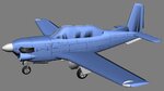
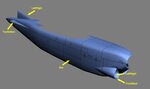
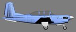
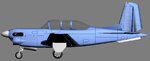
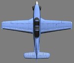
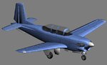
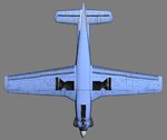
On this one, with scale rivets going around the fuselage from all angles, it is similar but not quite as bad (no concave recesses). The attached picture shows how it was mapped. The majority of the fuselage is box mapped, giving two sides, a top, and a bottom. The extensions for the tail feathers are mapped Top/Bottom or Left/Right as needed for minimal distortion. The intakes have the lip mapped Front/Back, while the interiors are mapped Left/Right.

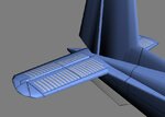
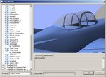
To get everything to line up, I build a template on a temporary layer before drawing the real rivet lines (which is what I was alluding to a couple of posts ago). On this template I use vector lines that can be easily moved and adjusted. But there is a whole lot of going back and forth between Max and PSP to make adjustments, literally pixel-by-pixel at times. I get them all aligned and in the correct location, then I create the rivet layer by placing the rivets over those lines. The final laying down of the rivets goes pretty quickly, but you have to watch the scale of the parts. In Max's UVW editor (at least in my version) there does not seem to be a way to scale things to an exact amount. So the tail feather extensions are about 80% of the scale of the big fuselage section and not by my choice. I just did not want to try and go back and remap them to get them closer and still not be exact.

Doug
 

Attachments

  • Image14.jpg
    Image14.jpg
    71.9 KB · Views: 25
Top of the wings have been done. Riveting, isn't it :p
 

Attachments

  • Image15.jpg
    Image15.jpg
    143.1 KB · Views: 25
Heeleycopter said:
I've been tryin to figure out what modelling software you use?
For the quick & dirty modeling, I use Wings3D. For the final modeling, pivots, links, and rendering as I do the colorscheme I use 3DSmax. Colorschemes are done with Paint Shop Pro (which can use the nVidia Photo Shop plug-ins to do Normal maps).

Before you ask, I know Wings is not as capable as Max and it may seem odd that I use it when I have the vastly more powerful program. But I view modeling simple aircraft in Max to be like trying to take a sip of water through a fire hose. The program is too powerful, and I can make a low-polygon model with Wings in 1/4 the time it would take me to do the same model in Max.

Doug
 
You guys must all be asleep... I can't believe I got away with that stinker without someone making a comment. :D
 
OK other than for the gear doors, I think I've finished the exterior detailing on this model. I think it's time to take a break and go work on a real model for a while.

Doug
 

Attachments

  • Image18.jpg
    Image18.jpg
    36.5 KB · Views: 8
  • Image19.jpg
    Image19.jpg
    37.5 KB · Views: 5
  • Image20.jpg
    Image20.jpg
    53.4 KB · Views: 12
  • Image21.jpg
    Image21.jpg
    50.1 KB · Views: 14
  • Image22.jpg
    Image22.jpg
    55.5 KB · Views: 9
Last edited:
Just a guick import into RF to see how the Normal map for the rivets would render.
 

Attachments

  • Image23.jpg
    Image23.jpg
    86.2 KB · Views: 24
Alright guys, I need a vote before going any farther (but I'll refrain from using a poll). Look at the tail - too shiny or not?
 

Attachments

  • Image24.jpg
    Image24.jpg
    69.6 KB · Views: 34
Back
Top