
You are using an out of date browser. It may not display this or other websites correctly.
You should upgrade or use an alternative browser.
You should upgrade or use an alternative browser.
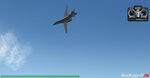
The B-1B Lancer
- Thread starter mwilson914
- Start date

Norton
New member
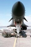
They are called canards.
"The Canards smooth out the "stresses" on the forward fuse. They have little if anything to do with the handling of the plane"
"The length of the aircraft presented a serious flexing problem due to air turbulence at low altitude. To alleviate this, Rockwell included small canards near the nose on the B-1. An accelerometer would actuate the canards automatically to counteract turbulence and smooth out the ride"
Last edited:
mwilson914
Well-known member
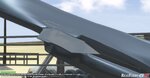
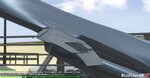
Norton said:Those fins are stationary and there not movable canards.
I have some contradicting info about those fins/canards. I at first noticed what appeared to be a pivoting base on the fin earlier on and I have some info that they do move a bit for stabilization.
In the pic you can see what is circled on close examination:
Attachments

mwilson914
Well-known member
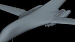
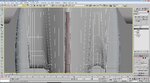
I got a test model loaded up into RF this evening. It looks like vomit, but I'll figure out what is wrong with it. I'm not sure why it looks awesome in Max, but bad in RF. I did perform a mesh smooth modifier to see what the result would be on a second version. It looks much better, but moving around on the ground, there are some weird artifacts which flicker around. I checked that I didn't accidently put two UVW maps, one on top of the the other, and it doesn't appear that is the issue, but I will clear all UV unwrapping with the modifier and then re-apply a fresh map to see what the result outcome is.
If the outcome is still BLAHHHHHHHHH, then I will need to rethink my strategy I became so proud of over the past two days. I'll post some detailed wireframe renderings too later tonight in case that info is helpful.
The 2nd picture from RF is the 2nd version with mesh smooth applied which adds an additional 7,000 polys to the model, so this is not an option for resolution.
The upbeat side to all this....it flies really nice with the basic physics. I'll make sure to mess it up as bad as I can before it's swap ready. I wouldn't want an aircraft to be too easy to fly.
Attachments
Last edited:
helohero
New member
I know you say stay away from the mesh smooth but I gotta ask the drawbacks of applying this to a model such as yours and then use multi res to take some of the polys out and keep the same basic look? I have had a discussion or two with others about this and would just like a better explanation. One wing on the 108 went from 6000 down to somewhere around 750 doing this while still getting the look I wanted. I know its cheating but is it acceptable in some cases?
I don't want to clutter up your thread with stupid questions but if I don't ask I guess I will never understand.
I don't want to clutter up your thread with stupid questions but if I don't ask I guess I will never understand.
Last edited:
mwilson914
Well-known member
helohero said:I know you say stay away from the mesh smooth but I gotta ask the drawbacks of applying this to a model such as yours and then use multi res to take some of the polys out and keep the same basic look? I have had a discussion or two with others about this and would just like a better explanation. One wing on the 108 went from 6000 down to somewhere around 750 doing this while still getting the look I wanted. I know its cheating but is it acceptable in some cases?
I don't want to clutter up your thread with stupid questions but if I don't ask I guess I will never understand.
You're not clustering up my thread and your question is certainly not stupid. I like the chatter that goes on because I learn a lot from others. I can't say if there are any real drawbacks to smoothing, then multi-res to achieve your result. I experiment with a new technique on each model create because I'm still nowhere near an expert, so the more things I do, the more I learn techniques that work better or worse than others.
My mindset on the mesh-smooth tool, is that you aren't in nazi-like control over the form of the model's mesh. If it works better in some cases to get the final model complete as you want, then it is well worth it. I'll admit I'm a bit of a control freak and so I figure the more smoothness of the model I'm responsible for without using the smoothing operations, the better off I am. It's also better as a newbie to get the smoothest result possible before reaching for the mesh-smooth modifier. I'm a newbie, so it's better that I learn efficiency over shortcuts.
I think that is probably the best point about it all. The more efficient you are at modeling, the better off you are. Also, if you pay as much attention to the model as possible keeping it basic, simple and smooth, the less polys you'll use later on if you decide to use mesh smooth.
As for my B-1, well, I tried a technique that obviously didn't work out so nice in Realflight. It looked really smooth in 3DS Max, but horrible in the sim. I completely revamped the mesh last night and I am re-starting the shaping of that bad section of fuse. I spent a bunch of time, just making the mesh simple and primitive again in that section. Basically, I prepped it for shaping again.
My lesson learned: Keep the rib sictions in their respective plane.
Last edited:
mwilson914
Well-known member
helohero
New member
I would like to learn from your mistake please enlighten me as to how you you achieved these miraculous results with such ease and efficiency as I feel they will be useful in the near future.
I also notice the symmetry tab selected I feel this is useful as well. This might be one of the answers I have been searching for.
I also notice the symmetry tab selected I feel this is useful as well. This might be one of the answers I have been searching for.
mwilson914
Well-known member
helohero said:I would like to learn from your mistake please enlighten me as to how you you achieved these miraculous results with such ease and efficiency as I feel they will be useful in the near future.
I also notice the symmetry tab selected I feel this is useful as well. This might be one of the answers I have been searching for.
Symmetry is awesome! I usually have a huge stack of modifiers too, but I need to bridge edges together after I detached the vertical stab from the rest of the fuselage and you can't do it with just the edit poly modifier. You actually need to convert to an editable poly, which is disappointing.
My other little secrets to learn from:
As far as how I go about editing the mesh with "ease", I select edges I want to get rid of and press crtl+backspace. I use the cut tool on either the poly or vertex subobject level to create new edges. Target weld is awesome welding vertexes together, as I just started using this finally.
To cap in holes that are near planer geometry, I use the "cap" command in the border sub-object level. (this is different than the cap holes modifier. The cap holes modifier will go after any and all surfaces it thinks is a hole, where as the cap command only fills in the border you select. A hole that has a complex non-planer border such as the rudder cut out of the vert, I bridge the edges with the "bridge" command on the edge sub-object level.
mwilson914
Well-known member
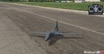
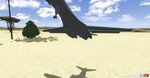
It's been a short while since my last update, but I've got a little more done. I still have some minor defects I need to take care of in the main fuselage, but I know I just need to select 3 sections of polygons and "slice plane". That will take care of all the fuselage defects.
I've been working on the landing gears and the wing control surfaces. I'm having a heck of a time with it too. For some reason, I can't get my steering gear doors to work, at all. I have setup complex systems on both the B-58 and the Gripen and have gone over the B-1 in comparison to my other models and I can't spot the problem. I will keep investigating the issue, but at some point I may need to ask for assistance from the masters.
Also, the main wings have a major issue like another swept wing aircraft available on the swaps. The B-1 does the same thing as the F-14 when the wings are swept back. It rolls really bad with elevator input and I've checked my control surface operation. I don't think RF's physics calculates how to handle main wing orientation changes properly. Yes, the physics can be fudged, but I am a person that tries to keep them as dead on as I possibly can. I want it to work correctly and nothing else.
Anyhow, here are some screenshots.
Attachments
Last edited:
mwilson914
Well-known member
Ok. HELP.
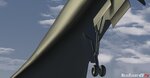
I'm going mad trying to figure out what is wrong. I haven't done the main gear doors yet, so could this cause my issue. I just wanted to test out the steering gear doors setup now. The main gear doors are scarier than the B-58 Hustler. Seriously, check out how the B-1B main landing gears function. It's very intimidating.
Back to my help request. Here are my NUP values currently on the B-1. I have rearanged them to be very simple, and exactly like the B-58 and exactly like the Gripen. The steering gear doors just won't retract still, so I have no idea what to do at this point.
B-1B LANCER NUP VALUES
~CS_SG
NUP_MaxRotationX=95
~CS_GD1_SGMAIN
NUP_MaxRotationX=95
NUP_LandingGear=~CS_SG
~CS_GD1_SGSTRUTA
NUP_MaxRotationX=-78
NUP_LandingGear=~CS_SG
~CS_GD1_SGSTRUTB (Child of Strut A)
NUP_MaxRotationX=34
NUP_LandingGear=~CS_SG
~CS_GD2_SGLEFTDOOR
NUP_MaxRotationY=-90
NUP_LandingGear=~CS_SG
~CS_GD2_SGRIGHTDOOR
NUP_MaxRotationY=90
NUP_LandingGear=~CS_SG
If you see anything that just doesn't look right let me know, but everything is hierarchy'd to the fuselage, with the exception of strut B.
Last edited:
mwilson914
Well-known member
mwilson914
Well-known member
Unfortunely, I have tried this at the most basic level with the first gear door attached as part of the ~CS_SG object, which of course closes because it's part of the SG. The left and right SG doors still l will not close. I deleted the supporting strut, so it would be as basic as humanly possible. I even copied the SG left and right doors and put them in the rear of the fuse and assigned each one it's own NUP value, changing what gear they follow to LG for the left and RG for the right. Those gear doors close!
The SG gear doors just will not close for the life of me and everything is correctly data filled. It's really bumming me out because it's a simple operation and it isn't working no matter how right it is.
Despite all this, I also tried what you said by naming the strut parts to SG2 and SG3, and also the actual sterring gear to SG1. Didn't work, so I tried SG_01, SG_02 and SG_03 and changed all the NUP values to reflect the correct data. Still nothing works.
I am beyond frustrated and can't do anymore on it right now. It is setup 100% correct from what I can tell. It's not hard to see if it's right or wrong, but I still am open to a "you did it wrong Matt." I would love that coming from someone else, but I just don't see anything wrong, especially since I copied the doors and they work on the back. All I did was edit the NUP values by changing the S to a L and an R for the corresponding gears. The dang thing flies and everything works except the SG gear doors. If the engines didn't respond, I would know what I did wrong, but nothing is wrong.
mwilson914
Well-known member
FIXED IT!!!!!!!!!!!!!!!!!!
I deleted the physics steering gear and entered it back in. Whalla!
I deleted the physics steering gear and entered it back in. Whalla!
nemo_uk
New member
A tip for you with regards smoothing. In object properties --> user defined in 3dsmax (same place as you define NUP_MaxRotationX etc.) you can put NUP_MaxSmoothingErrorDEG=70 You might need to experiment with the number at the end to get a good result. The piece of geometry must be named ~CS_ .....
eelleeccttrriic
New member
so whens this thing going to be out on the swaps?