Trident Redux

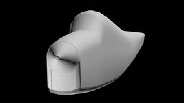
Looks great to me! Maybe feather fhe top/bottom curves into the flat sides a little more. There's actually a slightly sloped upper sheet above the flat sides behind the cockpit, making it pretty much egg shaped, fat end down. The actual flat fuselage sides are completely below the level of the cockpit. The flat sides feather into the curves as shown in the attachment. Did I send you the full plans, way back when? And there should be a little overhang at the top of the windshield - most visible in the "Santa2" photo above. I assume you 'll be hollowing out the area behind the rear cockpit bulkhead to resemble the cowl air outlets when you do them. Am I being too picky? I couldn't do what you've already done in a month of Sundays.
MAN_Fuse_Parts.jpg
 
Looks great to me! Maybe feather fhe top/bottom curves into the flat sides a little more. There's actually a slightly sloped upper sheet above the flat sides behind the cockpit, making it pretty much egg shaped, fat end down. The actual flat fuselage sides are completely below the level of the cockpit. The flat sides feather into the curves as shown in the attachment. Did I send you the full plans, way back when? And there should be a little overhang at the top of the windshield - most visible in the "Santa2" photo above. I assume you 'll be hollowing out the area behind the rear cockpit bulkhead to resemble the cowl air outlets when you do them. Am I being too picky? I couldn't do what you've already done in a month of Sundays.
View attachment 129488
Just to make sure I understand what you said.

1. The Spinner looks fine the way it is?
2. The Rounding down of the Fuselage from the Spinner to the Canopy is fine the way it is?

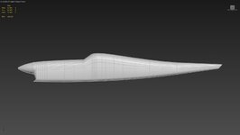
As for the fuselage shaping I haven't started it yet I just did an initial round off "but not the final shaping". So hold off on that part until I do it. Now for what I call the hard part, the "concave" cut-ins behind the engine and canopy. Here's the honest truth. Every time I try to cut-in areas like that I get lots of little flat spots around the cut-ins that look bad so I don't do them. I had the same problem trying to "cut-in" the engine vent doors on the T-28B I just did so I ended up scrapping the doors and just adding them to the "n-map" so at least there was something there. All this to say I'd rather have those areas look good and just be painted on instead of having little "flat spots all around the cut-ins" Which goes back "again" to me saying my modeling is just "so-so". So I end up doing things to make it look better than having cut-in areas that look bad with lots of little flat spots around them. Those little flat spots look terrible to me so it's better "not" to have the "cut-ins" than to see flat spots around them. Again being honest I can only "do what I can do" not what the other guys can do. But if one of the other guys (asj or legoman) wants to take over this plane to get all the details added I have no problem giving them my work so far and they could finish it.
 
Yes, the spinner looks fine to me. With regard to the other stuff, just do the best you can. I'm confident it will be "good enough." If the cutouts are painted on, so be it. If you're happy with it, I'm sure I will be, too. It's not like they're actually needed for engine cooling or cockpit ventilation in RF. IMHO, "stand-off" scale is fine. It's not like anyone will be examining it with a magnifying glass for a concourse award in RF like they do for C/L aerobatics.
 
Last edited:
Yes, the spinner looks fine to me. With regard to the other stuff, just do the best you can. I'm confident it will be "good enough." If the cutouts are painted on, so be it. If you're happy with it, I'm sure I will be, too. It's not like they're actually needed for engine cooling or cockpit ventilation in RF. IMHO, "stand-off" scale is fine. It's not like anyone will be examining it with a magnifying glass for a concourse award in RF like they do for C/L aerobatics.
Okay good I'll do the best I can. So the spinner and the round off of the fuselage is okay so the next time I work on it I'll start doing the final shaping of the fuselage. I'll probably do at least two or three more versions to get the fuselage shape finished. And yeah I know the fuselage above the canopy is sort of oval shaped. I'll try to get the overhang on the top of the canopy too.
 
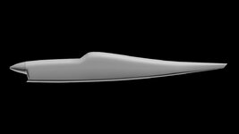
Looks great. Can I see a side view? I can't see the "chin" very well. In that view my gut says that the sides of the front opening need to be cut back a bit leaving a distinct chin. The front of the chin (lower jaw?) is actually even with the spinner ring. In your attachment, it looks like it might be dropping straight down, cutting off the chin. Take a look at outboard.jpg in my previous post. It's a pretty distinctive feature that I don't recall seeing on any other aircraft, and the bottom & sides scoop extra air into the cowl opening over the cooling fins like a rectangular funnel. It reminds me of a REAL shark's mouth rather than a P-40's painted on teeth. The sides look right, but it might need a little work on the bottom. Am I nitpicking to much? I definitely don't want to discourage you by being too picky.
 
Last edited:
It's much more obvious in that view. I guess the angle and the unfinished interior opening in the other view kept me from picking it up. It could maybe stick out a little more, but it's pretty darn good!
 
It's much more obvious in that view. I guess the angle and the unfinished interior opening in the other view kept me from picking it up. It could maybe stick out a little more, but it's pretty darn good!
What do you mean stick out more? Do you mean move the bottom a little more forward but leave the angle the same? Also you said the bottom might need a little more work, so give me an idea of what needs to change on the bottom.
 
A little more forward I think. The cowl started out as a solid block butted against the spinner ring & then hollowed out & shaped. And there's no "inner bottom" in the opening. I guess I'm used to seeing an engine in there, and the slope of the chin extending all the way up on the inside like nose.jpg in my photos post. The chin is actually pretty thick. But that might be one of those concave problems that you don't like. It certainly won't be very visible in the air, and it may not be worth worrying about, especially until you drop an engine into it. But I think that's one of the sexier details of the design - another example of the contrast between the sharp angles & gentle curves.
 
Last edited:
A little more forward I think. The cowl started out as a solid block butted against the spinner ring & then hollowed out & shaped. And there's no "inner bottom" in the opening. I guess I'm used to seeing an engine in there, and the slope of the chin extending all the way up on the inside like nose.jpg in my photos post. The chin is actually pretty thick. But that might be one of those concave problems that you don't like. It certainly won't be very visible in the air, and it may not be worth worrying about, especially until you drop an engine into it. But I think that's one of the sexier details of the design - another example of the contrast between the sharp angles & gentle curves.
I'll move the bottom of the chin forward so it lines up with the tip of the fuselage. The cowl opening where the engine goes is thick maybe you're not seeing it. And I still have more tweaking to do after I install the engine. Now the cowl needs both sides and top and bottom for the 3d model in RealFlight because if there's only one layer of polys you see though the inner polys to the outside. So the back of the cowl opening will be recessed to behind the engine when I put the engine in and of course the cowl will be painted black. I think once I put the engine in you'll like it. I tend to post small increments so things get better as I go. Maybe I shouldn't post such small increments.
 
I'll move the bottom of the chin forward so it lines up with the tip of the fuselage.
Sounds right to me.

I LOVE the frequent posts! With everything white, a lot of the details are hard to see, and I probably just misinterpreted what I was seeing. YOU know the details, and I don't. Keep up the fantastic work!
 
I went back and did two things to the chin.

1. I moved the front of the chin forward a little.
2. I moved the back of the chin back a little which increased the angle.

Small changes but you can see them.

Trident 09 (after).jpg
 
Looks great. Thanks. Now it needs that sub-rudder & tailwheel. Will that be part of the fuselage, or will it be a separate component? It doesn't deflect with the other 2 rudders, so I'm guessing it should be part of the fuselage. Well I'm guessing that it doesn't deflect in the R/C conversion but certainly doesn't for C/L. But maybe it should for ground handling and yaw authority since it's in the propwash and the outboard rudders probably aren't. I could easily be wrong about that.
 
Last edited:
Looks great. Thanks. Now it needs that sub-rudder & tailwheel. Will that be part of the fuselage, or will it be a separate component? It doesn't deflect with the other 2 rudders, so I'm guessing it should be part of the fuselage. Well I'm guessing that it doesn't deflect in the R/C conversion but certainly doesn't for C/L. But maybe it should for ground handling and yaw authority since it's in the propwash and the outboard rudders probably aren't. I could easily be wrong about that.
Remember this is an extension of the Trident I already made so everything that was in the first one is in this one too. But I hide components I'm not working on. The sub-rudder doesn't deflect but the tail wheel does turn. The sub-rudder is a separate part it's parented to the fuselage but it's not part of the fuselage. (just like the first one)
 
Those are details I didn't pick up on, especially about the steerable tail wheel. But that also implies that you shouldn't need to do much to the sub-rudder assembly. It shouldn't need to change much (if at all) going from profile to built-up fuselage. That far back, the fuselages probably aren't much different.
 
Those are details I didn't pick up on, especially about the steerable tail wheel. But that also implies that you shouldn't need to do much to the sub-rudder assembly. It shouldn't need to change much (if at all) going from profile to built-up fuselage. That far back, the fuselages probably aren't much different.
I just made a copy of the original Trident and I'm only reworking the parts that's changing. Mostly just the fuselage.
 
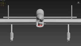
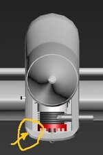
@Bill Stuntz I rotated the engine to be inverted and deleted all the parts I didn't need (fuel tank, servo, and tuned pipe). So here's a picture with all the parts shown so you can see what it looks like. I still haven't reshaped the top of the fuselage but I'll reshape it soon but I wanted to see how the engine fit in the new fuselage. So take a look at this picture and let me know what the engine looks like to you, most importantly how far the needle valve and muffler sticks out. I'll add the holes in the bottom of the muffler later but right now it's just there to gauge how far it sticks now. I eyeballed your picture but you'll be a better judge than me. Oh I'll change the color of the head and cylinder later so it looks like a normal all aluminum engine. Another thing, is the wing to thick?

Trident 10.jpg
 
Last edited:
Looks pretty close to perfect to me.
But I'm having trouble figuring out how to describe what I see as a relatively minor problem with the chin. I THINK I'm seeing the chin at the fuselage sides continuing more-or-less straight where the fuselage curves inward toward the spinner. It should actually be a smooth continuation of the fuselage curve if you're looking down from the top - it shouldn't stick out. I think I'm seeing a "shelf" there that doesn't belong - probably because the black triangle in outboard.jpg is hollowed out like the air outlets, making it look like an open shark's mouth. What I think I'm seeing would be like a shark with an overbite when he closes his mouth. Also, the bottom corners of the cowl opening should be rounded, pretty much like looking into a VERY shallow rounded-corner rectangular funnel with a huge opening at the bottom instead of a narrow neck. I hope I've managed to describe it clearly enough.
P.S. Maybe like about a 1/4" or 3/8" triangular gusset inside, with the long side concave. Without it, that corner wall/joint will be too thin with the outside rounded off. The wall thickness should stay about the same around the corner.
Trident 10.jpg
 
Last edited:
Back
Top