What is the naming convention for multiple rudders?

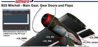
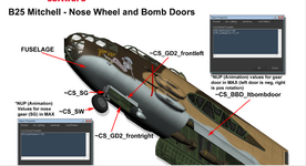
About the gears, yeah I think you mean separating it into two pieces like gear door and gear itself. I will do it as soon as I learn how gear doors work(how I should set their axes-where should X,Y,Z look for gear itself and gear door for example.).

I am a having a bit of problem with the original .blend file to be honest. It was extremely(maybe unnecessarily) detailed and has really high polygon count. I deleted tons of stuff from inside the fuselage. I checked how to reduce face/polygon count while keeping geometry intact with Blender's Decimate feature but it didn't seem to work. For anyone that is interested, I am uploading .blend file and the original texture files themselves here.
two or more. the gears and each gear door would need to be it own object so they can close and retract on there own axis
 
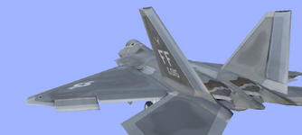
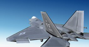
About the rudder, I downloaded what I uploaded to this topic and axes seem to be correct for .fbx file. X axes for both rudder travels along the control surface and in general upper direction. In electronics tab, I defined a single rudder. When I give rudder left command, shouldn't both rudders turn left? Am I missing something about flight mechanics?
If you have a single vertical stab and rudder then the naming convention is ~CS_MMVS, (Main Middle Vertical Stab) and ~CS_MMR (Main Middle Rudder), when you have twin stabs and rudders the rudder axis becomes negative for left side and positive for right side, the same will apply in general to main landing gear and gear doors.
 
the left rudders operate like the other left side control surfaces (pointing towards the fuse)
View attachment 140130

right side surfaces and non symmetrical surfaces point away
View attachment 140132
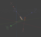
Can you a bit clarify. As far as I know, all control surfaces should move along the x axis. And according to the knife's edge tutorial, I just rotated the axes in a way that Y still points towards nose-ish, but X is along rudder's surface and since rudder is vertical, X looks up.

Another discrepancy between our screenshots is, I still see left rudder's X upwards instead of downwards. I am opening the fbx file. Can you download my model from scratch and check with Blender(if you have, I don't know which software shows you my positive X axis downwards.)
1721764582220.png
 
If you have a single vertical stab and rudder then the naming convention is ~CS_MMVS, (Main Middle Vertical Stab) and ~CS_MMR (Main Middle Rudder), when you have twin stabs and rudders the rudder axis becomes negative for left side and positive for right side, the same will apply in general to main landing gear and gear doors.
So, for the left rudder +x should look downwards. Is there an up to date guide with this information so I don't fall into same mistake next time? This might explain why rudder doesn't work on flight- they might be canceling each other out.
 
Can you a bit clarify. As far as I know, all control surfaces should move along the x axis. And according to the knife's edge tutorial, I just rotated the axes in a way that Y still points towards nose-ish, but X is along rudder's surface and since rudder is vertical, X looks up.

Another discrepancy between our screenshots is, I still see left rudder's X upwards instead of downwards. I am opening the fbx file. Can you download my model from scratch and check with Blender(if you have, I don't know which software shows you my positive X axis downwards.)
View attachment 140133

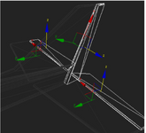
yes I opened your model in blender and made a few quick changes to show the corrected version.

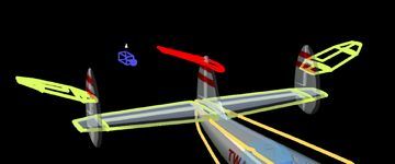
I have an example that might make a bit more sense my lockheed constilation has triple tails and I made some edits to show why left ruddes point "down". I rotated the (physics) rudders/stabalizers to 20 degrees instead of 90 (and moved them). the center rudder is non symetrical and is parrellel to the right rudder but the left and right are symmetrical and if you look at them as high dihedral wings you might be able to see why the left side points towards the root and the right side point towards the tip.
2024-07-23 15_23_17-Aircraft Editor - Lockheed L-1649 Starliner.png

So, for the left rudder +x should look downwards. Is there an up to date guide with this information so I don't fall into same mistake next time? This might explain why rudder doesn't work on flight- they might be canceling each other out.

there is no modern tutorial. yes the left rudder should point down

yeah they might be canceling each other out. when you are in the editor look at the outline physics and make sure the the rudders (physics) are going the same way (not crowing/airbraking)
 
yes I opened your model in blender and made a few quick changes to show the corrected version.

I have an example that might make a bit more sense my lockheed constilation has triple tails and I made some edits to show why left ruddes point "down". I rotated the (physics) rudders/stabalizers to 20 degrees instead of 90 (and moved them). the center rudder is non symetrical and is parrellel to the right rudder but the left and right are symmetrical and if you look at them as high dihedral wings you might be able to see why the left side points towards the root and the right side point towards the tip.
View attachment 140137


there is no modern tutorial. yes the left rudder should point down

yeah they might be canceling each other out. when you are in the editor look at the outline physics and make sure the the rudders (physics) are going the same way (not crowing/airbraking)
ah kk, you showed me how it should be. Got it. Yeah, is there any effort we can create a pinned thread for the information that is not in the "official" knife's edge guidelines? I know Realflight should provide it but in the meanwhile, we can immortalize some modern information. For example, normal guides are suggesting Horizontal stabilizer should exist as parent of elevator in the .fbx model to import. However, I directly parented elevator to fuselage without creating a shell horizontal stabilizer object. Realflight took it like a champ. This info can also into that FAQ's object parental section.

I corrected the left's local axes. It might be confusing because of the perspective but left rudder X points down-ish now.
1721818230194.png

And here are the model with updated rudder axes
 

Attachments

  • F-22.zip
    9.2 MB · Views: 2
Last edited:
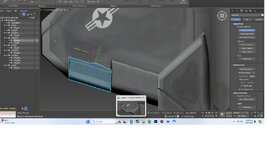
Needs the pivot points setting for right and left ailerons and flaps, the red X axis should point along the hinge line, notice that when these control surfaces are operated the part does not stay "hinged" to the wing, the ailerons and flaps tilt on the hinge line (see pics) Picture #1 shows aileron hinged to wing, picture #2 shows the aileron twist.
I just rotated the pivot point in 3dsmax to follow the hinge line, (see pic.)
 

Attachments

  • Aileron hinge .png
    Aileron hinge .png
    359.4 KB · Views: 7
  • Airleron hinge tilt.jpg
    Airleron hinge tilt.jpg
    89.4 KB · Views: 7
  • pivot point rotated.jpg
    pivot point rotated.jpg
    285.3 KB · Views: 7
Needs the pivot points setting for right and left ailerons and flaps, the red X axis should point along the hinge line, notice that when these control surfaces are operated the part does not stay "hinged" to the wing, the ailerons and flaps tilt on the hinge line (see pics) Picture #1 shows aileron hinged to wing, picture #2 shows the aileron twist.
I just rotated the pivot point in 3dsmax to follow the hinge line, (see pic.)
I totally know what you mean, will fix it. I didn't show enough attention to those poor ailerons, flaps, elevators as much as rudders.
 
  1. I fixed misaligned axes for reamining control surfaces
  2. I separated door objects from landing gears and parented all of them to fuselage(all landing gear are parented to fuselage as well). So they are like siblings
  3. I properly named them
  4. Put pivots to the middle of the edges where they touch to the fuselage
  5. I added NUP max rotation properties and nup landing gear properties to all landing gear and gear doors
  6. I didn't rotate local axes of any doors. all of them are aligned with fuselage. The guide you suggested about landing gear doors also don't touch axes.
  7. When importing this plane, it says import successful but selecting the plane crashes the game to desktop. There is no logs under Logs folder. Restarting game removes the imported plane.
If you could take a look at my fbx files, I would appreciate it. I am uploading both doors and no doors version. No doors version doesn't crash and flies.
 

Attachments

  • DoorProblem.zip
    6 MB · Views: 4
I am moving the discussion since the nature of original problem has changed.
 
Back
Top