You are using an out of date browser. It may not display this or other websites correctly.
You should upgrade or use an alternative browser.
You should upgrade or use an alternative browser.
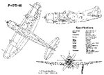
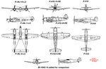
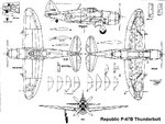
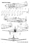
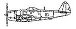
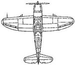
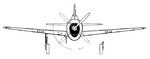
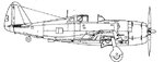
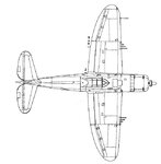
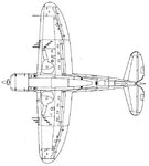
P-47 3 way veiw
- Thread starter WingDude
- Start date

pplace
Well-known member
In Wings3D:
1. Right Click then select "Cube"
2. Select entire cube, Right Click then select "Scale" then select the top choice in the sub menu.
3. Scale up accordingly. To check the size switch to the "node" triangle (the furthest left triangle in the upper menu bar) then select the top two corners of the box........in the upper left corner of the screen you will see the "information" It will tell you what "vertices's" are selected and the distance between them.
4. Scale it up or down until the distance is what you want your final wingspan (in inches) set at.
5. At this point in the Geometry Graph set the BB to "invisible...or see through so only the edges are visible.
6. Now place your top view of the 3-view plans in place.......scale that up the same way until the tips of the wings are at the edges of the bounding box.
7. From there you can move the top or front of the BB in or out to match the front, top, back and bottom of the 3-view plans if you want. But the Wingspan distance is the only thing that matters.....so this is an unnecessary step
8. From here you won't need t BB anymore
pplace
Well-known member
WingDude said:whats sub menu?
when you right click and move your mouse over the first menu that pops up....if there are more options for a specific task it will slide open another "sub menu"
pplace
Well-known member
scale the box...then set the wingspan of the top 3-view to the bounding box
from there you can pretty much delete the bounding box and just line up the side and front 3-view to match the top 3-view
The only thing the bounding box does is help you set up the "size" of your model
from there you can pretty much delete the bounding box and just line up the side and front 3-view to match the top 3-view
The only thing the bounding box does is help you set up the "size" of your model
pplace
Well-known member
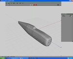
WingDude said:I have the fuse made, i think the cockpit is to wide but when i scale it it makes the fuse all massed up, is there anyway i can make it thiner without making the fuse look miss shaped?
I don't exactly understand what you mean? Are you switching to the "vert" triangle? Meaning are you only working with the individual "verts" or "nodes" (the little black squares) If not you will need to do that to start refining your fuse / cockpit shape.
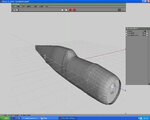
Also at the rate you are going........you will be out of your 20,000 poly limit before you know it!!! Each "connection" or segment you are adding bumps the poly count up. It looks like you started your "cylinder" with too many segments to start with (Usually the default of 16 segments/sections will be fine) And each vertical segments you have......on a model such as that you'd could probably get by with 10-15?? You have countless numbers........(alone on the front section of the cockpit there must be 20?)
Remember to go back and view some of the other modelers "WIP" threads or dhk79's FW-190 build can be found under the "sticky" section....you will see how "rough" the model can look......and still come out looking fine
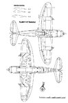
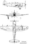
Take a look at the FW-190 I'm building. In the first post I have 3 pictures of one.....one is directly from the side. You can see how few of vertical segments I use (I think there are 10-12) and the fuse cylinder started with 16 also
pplace's FW-190A build thread
Good Luck
Last edited: