Airplane Tutorial
Jump to
Overview - How does RealFlight work?
When importing a model, RealFlight will look for specially tagged objects, hierarchies, and pivots to determine how to manipulate a model in-game. We'll cover the basics of rigging a vehicle and then explore some advanced topics towards the end:
![]() Naming Convention - A specific naming convention is used to identify and distinguish unique components of a model: wings, landing gear, etc.
Naming Convention - A specific naming convention is used to identify and distinguish unique components of a model: wings, landing gear, etc.
![]() Linking Hierarchy - The link hierarchy of the model is responsible for setting up an association between parts such that RealFlight knows which components belong to which parent object (i.e. a landing gear could be attached directly to the fuse, or alternatively it could be attached to a wing). This hierarchy is used during break-apart to detach a component and all other parts parented to that part. For example, lets assume we have a plane that has landing gears attached directly to the wings. When the wing is broken off, the landing gear will be broken off along with its parented wing.
Linking Hierarchy - The link hierarchy of the model is responsible for setting up an association between parts such that RealFlight knows which components belong to which parent object (i.e. a landing gear could be attached directly to the fuse, or alternatively it could be attached to a wing). This hierarchy is used during break-apart to detach a component and all other parts parented to that part. For example, lets assume we have a plane that has landing gears attached directly to the wings. When the wing is broken off, the landing gear will be broken off along with its parented wing.
![]() Pivots - Finally, pivots need to be oriented correctly so that movable components, such as control surfaces, will rotate around the correct axis.
Pivots - Finally, pivots need to be oriented correctly so that movable components, such as control surfaces, will rotate around the correct axis.
Following the basics, we'll cover special cases on how to setup basic propellers, landing gears, and movable control surfaces.
A Few Details First
The first step is to determine the units and scaling that will be utilized. Although it is possible to scale the aircraft within the simulator, we recommend that you setup your mesh according to scale within 3dsmax. Doing so will help avoid any scaling issues that may arise in-game.
Next, verify the world center. The [0,0,0] world location will be the default Center of Gravity (CG) for the model. While the CG may be refined in-game, we suggest that you set an approximate CG location prior to exporting the model. Note that changing settings in the aircraft editor will modify the CG location.
With the model centered and scaled correctly, let's take a look at how to break the mesh down into components that RealFlight will recognize. Because RealFlight will be looking for named meshes, we can divide the mesh up into logical segments such as fuselage, wings, control surfaces, etc. These meshes will then be tagged for later use by RealFlight to uniquely identify each of those components in the Aircraft Editor. Lets cover the naming convention in a little more detail.
Naming Convention
Each component which will later need to be identified in the Aircraft Editor must be named using the following convention. The naming scheme, used to identify a part, is ~CS_PARTNAME where PARTNAME can be almost anything that identifies that part. Certain names are reserved for special functionality and will be covered later on. The name you specify here is the name that will show up later (in the aircraft editor when setting up your model in-game). It is a matter of personal preference whether you include the complete name or if you simply wish to use an abbreviated version of the name. Here is an example that shows how a typical aircraft is tagged.
Review the Reserved Names section before naming parts of your model to avoid naming conflicts that might cause unexpected behavior.
Note that when a mesh is exported with unnamed or improperly named parts, those parts will be merged as either the root (typically the Fuselage) or whatever parent they are linked to. Those parts will not exhibit any unique behavior in-game except information they inherit from their parent (i.e. part will not be animated, part will not break off unless parent part breaks off, etc). Parts that share the same name will also be treated as one object (i.e. if both left and right wings are named the same: ~CS_Wing RealFlight will only see one wing object).
As a tip, parts can be individually named OR placed in a group. RF will treat groups as one named mesh. Avoid nesting named meshes inside groups as the results may be unexpected.
Link Hierarchy
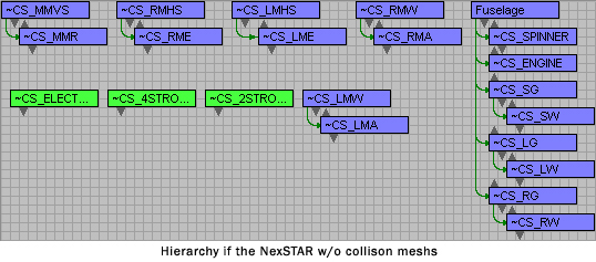
A link hierarchy must be established between all named objects. The link hierarchy describes how different parts of the vehicle are parented to one another. For example, an aileron is parented to a wing; a wing is parented to the fuselage. The image below shows the link hierarchy of the NexSTAR (please note that collision meshes for this plane are hidden for simplicity).

(Click on the image to enlarge.)
Objects that are not linked to anything will automatically be parented to the Fuselage.
Example of a poor hierarchy:
On the P51 model, if the front landing gears are NOT parented to anything, they will, by default, be parented to the fuselage. In-game if a wing breaks off (in a crash), the landing gear will appear to be floating next to the fuselage of the plane because they will not get broken off with the wing.
Pivots
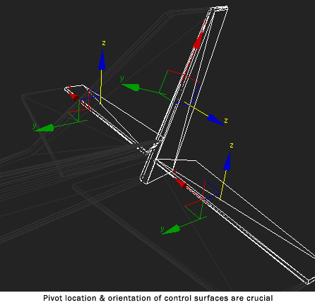
For most objects, pivots should be setup at the center of the object in the same orientation as the world axis where the Y-axis points towards the front of the vehicle. The pivots' orientation and location are especially crucial on objects that are movable. RealFlight will move/animate components along the pivot orientation, therefore it is important to setup them up correctly on the following components:
Control Surfaces (Ailerons, Elevators, Rudders)For control surfaces, the X-axis of the pivot denotes the axis of rotation and should therefore be aligned precisely with the edge of the mesh (or wherever it is articulated). Note how the X-axis of the rudder is going along the axis or rotation.
Wheels
Retractable Landing Gears
Engines & Spinners
Symptoms of an incorrectly-oriented pivot could be wheels spinning in reverse, control surfaces moving backwards, etc. These issues are easily fixed by rotating the pivot point of the objects.
Reserved Names
As mentioned above, certain names are reserved for special functionality. These are names that RealFlight looks for specifically to cause certain behaviors like dynamically placed propellers. The following sections will cover some of the items that require unique names.
Propeller & Engine Setup
RealFlight dynamically creates propellers on the aircraft. While the propeller mesh and number of blades are specified in the aircraft editor, the placement of the propeller is determined by a named object in the model itself. The pivot point of this object determines the location where props are created. The mesh itself can be anything since it is not actually rendered in-game, however it is typically represented by a ring or propeller blades. This mesh MUST be named ~CS_ENGINE.
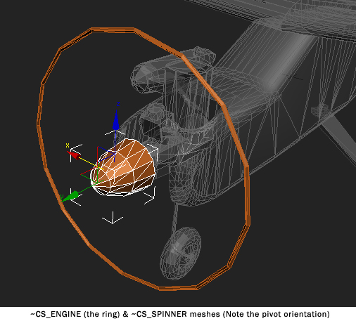
The spinner of the aircraft should be named ~CS_SPINNER. RealFlight will automatically animate the speed of the spinner based on the engine RPM.
Both the ~CS_SPINNER and ~CS_ENGINE should, by default, be linked to the Fuselage for most single engine aircraft. Some multi-engine setups require that these components be linked to other parts of the mesh such as the wings.
Landing Gears & Wheels
RealFlight supports both tricycle and tail dragger landing gear setups. Each gear set consists of two parts, a gear and wheel. The wheel must be parented to the gear (so when a gear breaks off, the wheel will detach with it) and the gear can be parented to the Fuselage or any other component such as a wing. RealFlight will automatically rotate the wheel as the vehicle taxis on the ground so pay attention to the pivot orientation of the wheel. The naming convention for these components are:
~CS_SG, ~CS_SW Steering Gear & WheelRealFlight does not distinguish between tricycle and tail dragger setups. Instead, it uses the physics of the plane to determine how it should rest on the ground. Therefore, the placement and location of the CG will have an effect on the stability of the plane as it sits on the runway. On a tail dragger, if the CG is placed in front of the front landing gears, the plane will NOT be stable on the ground.
~CS_LG, ~CS_LW Left Gear & Wheel
~CS_RG, ~CS_RW Right Gear & Wheel


(Click on the images to enlarge.)
Retracts & Gear Doors
Bomb Door Object Properties
The ~CS_BBD_ltbombdoor is a child of the FUSELAGE. The ~CS_BBD designation is different from the GD designation so that it can be assigned to a different switch on the InterLink Elite.
Gear Door 1 Object Properties
In this case, the ~CS_GD1_Leftgeardoor is a child of ~CS_LMW and has the same NUP_MaxRotation so it can close the same time as the gear.The GD1 designation always closes the door with the gear.
In some cases the gear door can be attached in Max to the LG/RG object for the same effect.

Gear Door 2 Object Properties
The ~CS_GD4_Lefttiredoor is a child of the FUSELAGE and has it's own NUP_MaxRotation so it can close after the gear.The GD4 designation opens the door then closes the door after the gear collapse or extend.

Landing Gear Object Properties
The ~CS_LG is a child of the Wing it belongs to. Its rotation is designated by the NUP_MaxRotation angle given in its Object properties. The rotation can be assigned on the X,Y or Z axis with positive or negative rotation degrees.
Special Door Object Properties
The ~CS_GD3 designation is almost the same os GD2 except there's a slight hesitation in the door on open and close.
Tail Gear Object Properties
The ~CS_SG is a child of the FUSELAGE. SG is for "Steering Gear". The doors for this particular gear are designated ~CS_GD2 left and right. they are children of the FUSELAGE as well.The GD2 designation makes the door wait for the gear to completely move then the door closes.

Springy Landing Gear
The Springy gear on most taildragger aircraft is set by calling an object on the tail ~CS_SG_SPRING. The pivot on this object sets the place where the tail gear springs from, or pivots. The Steering gear (~CS_SG) is a child of ~CS_SG_SPRING and has its own pivot point.

Collision Meshes
While optional, collision meshes help to reduce the computational complexity of the collision calculations and can significantly increase the performance of the simulation. RealFlight will look for any object that starts with the name ~CS_COLL. If any such parts exist, RealFlight will assume that set to be the full collision mesh for the vehicle. If any objects tagged as collision meshes exist, and if any part does not have an associated collision mesh, that object will not receive any collision information. Therefore, when using collision meshes, be sure that all critical named parts have an associated collision mesh.
A collision mesh should be a simplified, lower poly lattice that encompasses a particular component of the aircraft. In the example of the NexSTAR below, notice how most of the plane can be simplified down to very primitive objects. Also note that the collision mesh does not need to be super accurate.


(Click on the images to enlarge.)
Not all parts of the mesh need a collision mesh. For example, the ~CS_ENGINE component describes the location of the propellers. The mesh is just a place holder and does not provide any information about collisions and therefor does not need to have a collision mesh. Also, if the vehicle contains inner details like cockpit/pilot figures, those do not need any collision meshes since an outside surface will encompass that surface.
After a collision mesh is built for each object, it must be linked to whatever object it represents. The image below shows the link hierarchy of the collision meshes on the NexSTAR.
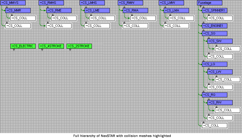
(Click on the image to enlarge.)
Note: To avoid complications during this process, build and test the plane in RealFlight before working on collision meshes. After the model is working and setup correctly in RealFlight, go back and add collision meshes. After adding collision meshes to model, test break-apart in-game to make sure everything is still working.
Material Naming
For texturing mapping your mesh, you may utilize one 32-bit tga. While only one texture can be referenced, there are no limits to the number of materials. Different materials should be used to specify differences in glossiness, and other parameters. It is also possible to create shaders that do not rely on the tga.
In order to utilize the transparency information in the TGA, the material name must include: ~ALPHA This tells RealFlight to use the transparency information for that material.
There are several special material tags:
ALPHA - As mentioned this enables the use of the TGA's alpha information.
SBS - Show both sides; this flag causes the mesh to be visible and textured from both sides. This useful where the inside wall of an aircraft is visible (otherwise it will look transparent from one side).
CANOPY - This is a combination of ~ALPHA and ~SBS. This is used for canopies where the glass is both transparent and visible on both the inside/outside.
BREAKAPART - This unique tag makes this material visible only after the part has been broken off. If the part is not broken off, the object with this texture will be invisible. This is used to cap surfaces that become visible after breakapart.
For an example of the different values of glossiness & specularity, check out the Samples Spheres example found in the samples folder.