
You are using an out of date browser. It may not display this or other websites correctly.
You should upgrade or use an alternative browser.
You should upgrade or use an alternative browser.
F-16 C Build Thread
- Thread starter Boof69
- Start date
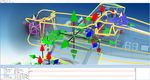
28 pivots around the tail nozzle, there are a lot of pivots on a simple model (as in the pic below) but jam in 28 more, Wow there are going to be a lot of pivot arrows packed into your viewport.
Please post a pic of the pivots when you are finished, that should be really interesting.
Please post a pic of the pivots when you are finished, that should be really interesting.
Attachments
Boof69
Well-known member
There's a trick for that. They will be added in the editor as retracts. In the model they will be children of an invisible helper object as you would do for retracts with doors. No arrows in the editor. I used this method with my Corsair F4U-1 for the 15 cowl flaps in case you want to check it out.
Attachments
Boof69
Well-known member
Well I have had a lot of issues with family health and computer health and a touch of laziness that has kept me from this project, but I am back on it now.
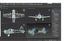
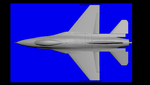
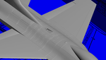
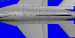
After fixing a problem with the cut tool in max (one of my most used tools) I decided to do modeled panel lines of which there are many. This is 85% of the top panel lines done. Polys are nearing 10k quickly and no landing gear yet, But I am not too concerned. Lots of polys left in the quiver.
After fixing a problem with the cut tool in max (one of my most used tools) I decided to do modeled panel lines of which there are many. This is 85% of the top panel lines done. Polys are nearing 10k quickly and no landing gear yet, But I am not too concerned. Lots of polys left in the quiver.
Attachments
uncle twist
Well-known member
WOW..!!! fantastic work/detail Boof, thanks for the update, were the panel lines extruded inward..???
uncle twist
Well-known member
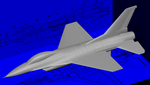
Thanks for explanation, Yeah, I imagine the smoothing groups would be pretty challenging, as is the whole plane for that matter. It`s coming along beautifully.Thanks guys. U.T. yeah they are made by outlining the panel then chamfering the edge from one line to 3 lines then selecting the center line and pulling it downward. Smoothing groups is the hardest part.
")
uncle twist
Well-known member
The detail should be visible like in a bump map for example, only better, I would think.Really nice detail. Are you making this model for something besides RF ? It looks very nice, but is it worth the work, when it won't really be seen ? I'm not knocking it, just curious.
Boof69
Well-known member
I am a detail addict. It's just how I'm wired. I've always wanted to do modeled panel lines and with the higher poly limit I can give it a shot. You're going to be real confused when I start the cockpit.Really nice detail. Are you making this model for something besides RF ? It looks very nice, but is it worth the work, when it won't really be seen ? I'm not knocking it, just curious.
abaser
Well-known member
I can attest to this statement. Boof has always added much more detail than ever thought of even with a 20k poly limit.I am a detail addict. It's just how I'm wired. I've always wanted to do modeled panel lines and with the higher poly limit I can give it a shot. You're going to be real confused when I start the cockpit.