Pilot RC J-10

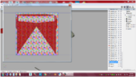
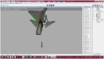
Correct. You are in complete control of how you position them. One tip would be to try to keep related parts sized relative to one another so graphics can be used across parts with out the need to resize. Also size them according to the detail you intend to add. My F-16 for instance. The cockpit will be much larger on the map than the exterior because it requires it more than the exterior.
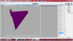
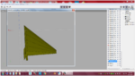
 
Andy, does wings work the same as max where you can map one half then copy the part and it will be mapped? Then allow you to mirror the new uv? It has to I would think.
 
Last edited:
Andy, does wings work the same as max where you can map one half then copy the part and it be mapped? Then allow you to mirror the new uv? It has to I would think.
Yes. I don’t remember off hand very much about the mapping process because I went to Max pretty quickly when it came to mapping. I’ll try to look at it tonight and refresh my memory though.
 
Yep that should solve your poly count problem.

Now about something you'll run into later because you deleted the polys "inside" the wheel wells. In realflight a polygon is normally "one sided" meaning from the outside you can't see through it and see the color scheme but from the inside it's transparent so when you look at the bottom of the plane in realflight you'll be able to see through the top of the fuselage because the polys are transparent because of being "one sided". To fix that you can create a material and name it "~SBS" (ShowBothSides) and assign the CS TGA file to that material. Once you've done that select the FUSELAGE and apply that material to the FUSELAGE. Then whatever is painted on the outside of the FUSELAGE will also show on the inside of it too. Which means if you have a yellow plane and look at the bottom of the fuselage in the realflight editor you won't be able to see through the top of the fuselage but the inside will be yellow like the outside. Of course you won't see through the fuselage if there's anything in the way like a wing or a duct. There is other ways to fix that like giving the fuselage an internal shell but that would cost a bunch of polys but you'd be able to paint the inside of the fuselage too, but that shell would need to be mapped. Maybe the other guys have a different solution but that's how I normally do it.
 
Last edited:
A general rule of thumb for me personally is that if it's at all possible to see backfaces in RF I will enclose that. So in Woodzy's case where the fuselage is opened up to accept the landing gear I would select that open boundary and Shift+move into the fuse about the thickness of the real life material. Then with the same edges selected I would use shift + scale to make a larger interior space, Shift+move up, then cap.
 
Pic 1: bottom mapped to UV 1
Pic 2: top mapped to UV 2
Pic 3: parts laid out on the map
Pic 4: wing shown in wings as mapped
Pic 5: In face select, select the root face that butts up against the fuselage. left click and RIGHT click mirror. This will create another wing with mapping coordinates as well. If you LEFT click mirror, it'll be attached to the original and you'll have to manually separate it.

Hope this helps a little. You can literally map ONLY half of the model and mirror the other half
 

Attachments

  • Screen Shot 04-29-20 at 06.27 PM 001.PNG
    Screen Shot 04-29-20 at 06.27 PM 001.PNG
    350.4 KB · Views: 12
  • Screen Shot 04-29-20 at 06.27 PM.PNG
    Screen Shot 04-29-20 at 06.27 PM.PNG
    343.7 KB · Views: 10
  • Screen Shot 04-29-20 at 06.29 PM.PNG
    Screen Shot 04-29-20 at 06.29 PM.PNG
    690.6 KB · Views: 13
  • Screen Shot 04-29-20 at 06.35 PM.PNG
    Screen Shot 04-29-20 at 06.35 PM.PNG
    417.7 KB · Views: 13
  • Screen Shot 04-29-20 at 06.36 PM.PNG
    Screen Shot 04-29-20 at 06.36 PM.PNG
    448.1 KB · Views: 14
A general rule of thumb for me personally is that if it's at all possible to see backfaces in RF I will enclose that. So in Woodzy's case where the fuselage is opened up to accept the landing gear I would select that open boundary and Shift+move into the fuse about the thickness of the real life material. Then with the same edges selected I would use shift + scale to make a larger interior space, Shift+move up, then cap.
So make wheel wells, right? I mentioned that because I thought he mentioned he deleted the polys inside the gear opening and was going to leave it that way because the real model was that way. Yeah I'd do wheel wells.
 
A general rule of thumb for me personally is that if it's at all possible to see backfaces in RF I will enclose that. So in Woodzy's case where the fuselage is opened up to accept the landing gear I would select that open boundary and Shift+move into the fuse about the thickness of the real life material. Then with the same edges selected I would use shift + scale to make a larger interior space, Shift+move up, then cap.
I'll add a cover inside over the gear which should solve the problem I hope!
I only deleted the inside faces to aliviate the shading issues.
 
Yes. You want the letters to be the correct way. Now, depending on how you lay your map out, they may be sideways, or upside down, but if you rotate your model, you should be able to read the letters correctly. Also, depending on the size of the part on the map, the letters may be larger or smaller. If the letters are backwards, everything on the tga will also be backwards on your model.
 
Yes. You want the letters to be the correct way. Now, depending on how you lay your map out, they may be sideways, or upside down, but if you rotate your model, you should be able to read the letters correctly. Also, depending on the size of the part on the map, the letters may be larger or smaller. If the letters are backwards, everything on the tga will also be backwards on your model.
ok so would this be an issue?
as there is size difference...Screenshot (218).png
 
If you plan on doing a CS where you’ll have graphics crossing from one part to another, you’ll want it al scaled the same size, and also lined up. Doesn’t necessarily Have to be the same letters, just the box edges. This is all for simplicity. You can get away with things not being the same size, but you’ll have to adjust when it comes to doing your CS.

Hope that makes sense.
Perfect sense thank you (y)(y)
 
Is this ever going to be finished and uploaded? Same goes for the FC-1

Not sure, the files are on my old pc. The j10 is on the swaps thanks to me entrusting someone with my original beta EA. But unfortunately, that person also sent it to other people who, uploaded it as their own EA.
 
Back
Top