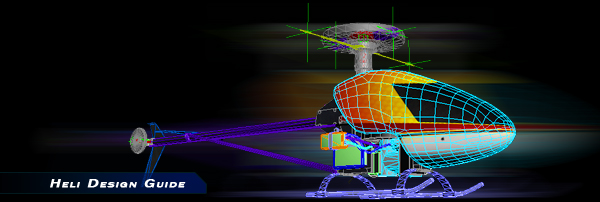
Helicopter Tutorial
Jump to
Designing Helis with KEmax
The fundamentals of designing and setting up a heli are the same as airplanes. What differentiates them is the added complexity of implementing the rotor blades. Because of the additional complexity of these vehicles we suggest that you work though several aircraft examples to familiarize yourself with the general concepts first. If you have not yet read the airplane tutorial, please do so here.
Please note that the use of collision frames is highly recommended for helis.
In addition to the parameters introduced with designing custom aircraft, there are additional heli-specific properties that we will be discussing below. Here are the sections we will cover. For additional information about designing helis, please refer to the included Example Heli or head over to the forums and present your questions there.
Tutorial Overview
![]() Heli Hierarchy - Describes the general setup procedures for helis.
Heli Hierarchy - Describes the general setup procedures for helis.
![]() Canopy & Accessories
Canopy & Accessories
![]() Stabilizer Fins
Stabilizer Fins
![]() Tail Boom
Tail Boom
![]() Rotor Setup - Each rotor must define how it will look and move. In addition to defining the location of the blades, Blur Disks must be implemented to represent the spinning head assembly.
Rotor Setup - Each rotor must define how it will look and move. In addition to defining the location of the blades, Blur Disks must be implemented to represent the spinning head assembly.
![]() Landing Skids - Helis allow you to define skids that flex under increased stress.
Landing Skids - Helis allow you to define skids that flex under increased stress.
![]() Additional Notes
Additional Notes
Note: If you are intending to only make minor changes to existing heli models (e.g. a new canopy), you can avoid the hassle of setting up the rotor heads by importing them from the example file. The Rotor Setup section is intended for those who want to build customized rotor heads and should only be done by those willing to handle the challenge.
Many of the properties discussed in these sections fall under the "Reserved Names" category. Please pay particular attention to the naming convention of these parts. If you unsure about how to name something, follow the naming convention used by the Example Heli.
It may be helpful to look at the Heli Example.max file included in the samples folder while going though this tutorial.
Heli Hierarchy
Helis have a lot of mechanical complexity compared to airplanes, and models may show off the internal mechanics in addition to the exterior of the heli. Because the canopy is more of an accessory to the heli, it is not considered the root of the vehicle. Instead, we use the mechanical guts of the heli (the frame, the mechanics, etc) as the Fuselage frame. This is labeled as ~CS_FuseDetails in the example heli.
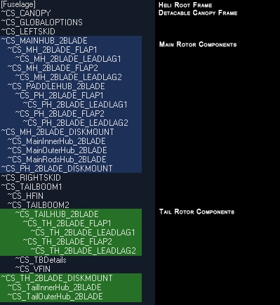
Below is the hierarchy for the Example Heli (collision meshes excluded)
If your model does not have internal mechanics, the exterior mesh may be used as the fuselage frame. Please note, however, that doing so will limit the breakapart capabilities of your mesh (see below). If the exterior of the heli has any transparent materials, consider including a "base" of some kind inside for added detail.
Canopy & Accessories
Uniquely identified parts of the heli can be broken off during a crash. RealFlight treats any fuselage component (different from the Fuselage mesh) as a component that can break off in a crash. We can utilize this on our canopies and additional parts to allow the heli to shed parts in a crash. The only requirement is to uniquely identify the part by giving it a ~CS_NAME. To enable the part to break off, from within Real Flight use the Aircraft Designer to add a "Fuselage Component", and associate the mesh with the new component.
To create a canopy that breaks off, name the canopy with a unique name like: ~CS_CANOPY. Follow the directions for adding a Fuselage Component in the Aircraft Designer.
Stablizer Fins
The Horizontal and Vertical Tail Fin components are similar to their counterpart stabilizers on airplanes. As such, all you need to do is name the parts using any unique name such as ~CS_VFin or ~CS_HFin. You can use these meshes in conjunction with a wing component to stabilize your heli.
These components should be linked to the appropriate locations on the boom.
Tail Boom
Tail booms are broken down into 2 segments called ~CS_Tailboom1 and ~CS_Tailboom2. These meshes include not only the boom, but also any supporting rods or control linkages that may be near/around it.
Pivots for each tail boom segment should be located at the point closed to the fuselage.
The tail rotor should attach the end of the boom.

(Click on the images to enlarge.)
Rotor Setup
Each set of rotating disks on a heli are all treated the same. They are all some form of a rotor head. The primary rotor on a heli typically consists of the blades and the paddle blades. In-game this is treated as two separate rotor heads.
Each rotor head consists of 3 parts -- the hub, the flaps and the leadlags. The hub is the primary rotor and is the root of any rotor system. Attached as children to this hub are flaps or the blade grips. These flaps can rotate around their local pivot to twist the blades used in varying the pitch. Finally, the leadlags define the location where the blades attach to the rotor heads. These are then linked to the flaps so that the blades will twist as the pitch of the rotor is varied. The basic hierarchy looks like this:
HUB --> FLAPS --> LEADLAGS
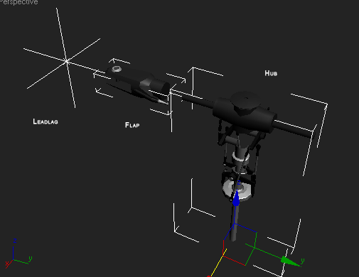
From right to left: ~CS_MAINHUB_2BLADE, ~CS_MH_2BLADE_FLAP1, ~CS_MH_2BLADE_LEADLAG1
These parts must be named using the unique naming tag described below. RealFlight identifies these parts by the name of the hub. In our case, the hub is called 2BLADE.
Main Rotor Hierarchy:
~CS_MAINHUB_2BLADE
~CS_MH_2BLADE_FLAP1
~CS_MH_2BLADE_LEADLAG1
~CS_MH_2BLADE_FLAP2
~CS_MH_2BLADE_LEADLAG2
~CS_PADDLEHUB_2BLADE
~CS_PH_2BLADE_FLAP1
~CS_PH_2BLADE_LEADLAG1
~CS_PH_2BLADE_FLAP2
~CS_PH_2BLADE_LEADLAG2
This image shows just the MAINHUB without the paddles attached.
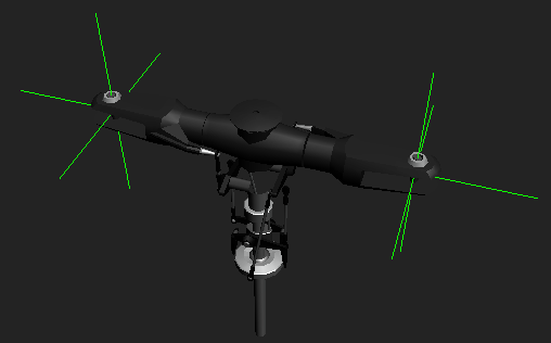
The paddles are integrated into the main hub as seen in this following image.

The tail rotor assemblies closely resemble the main hub without the paddle hubs. The tail hub is rotated 90 degrees off axis and tagged with the name: ~CS_TAILHUB_2BLADE. The Tail hub is linked as a child to the end of the tail boom so that in the event that the tail boom breaks off, the tail hub will be attached to the boom.
Blur Disks represent the hub when the rotor is spooled up at high RPMs. Each rotor must have an associated blur disk, or the hub will disappear when spooled up. Simply put, the blur disk is a collection of meshes that represent the hub. The blur disks start with a root node called the DISKMOUNT.
~CS_MH_2BLADE_DISKMOUNT
~CS_MainInnerHub_2BLADE
~CS_MainOutterHub_2BLADE
Any mesh linked to the disk mount will be treated as part of the blur mesh. As such, you can have multiple meshes that represent the spinning rotor.
For most of our helis, we started by creating a dummy node labeled as the disk mount. We then link our geometry to that node. A good place to start with these is to draw a path around the hub starting from the front view. Next, rotate it 90 degrees around the z axis and look at it from the side to make sure that the profile encases all of the hub. Use the lathe tool to create the blur disk out of this mesh.
In the case of the paddle hubs, the main hub's blur disk encompassed the paddle hub so it was not necessary to create any additional geometry for this rotor system.
Note: If the main hub consists of additional components like spur gears, the blur disk must encase all those components as well as the hub itself.
Finally, a view of all the components that make up the main rotor head.

(Click on the images to enlarge.)
Landing Skids
In addition to the wheel-based landing gears, you can also use skids on your helis. Because the skids will deform (bend) around the pivot point if a large enough force is applied on them, it is important to specify the pivot point around the point of flex/rotation.
The left and right skids should be uniquely tagged so that they can be associated with the skid component. For our helis we name the components: ~CS_RIGHTSKID & ~CS_LEFTSKID
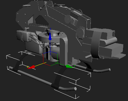
Note the orientation axis of the skid pivot.
Additional Notes
It is imperative that you utilize collision meshes to get optimal performance in-game. You only need to make collision meshes for the outer most parts of the heli (and parts that break off).
If your blades seem to be facing a strange orientation or are spinning in the wrong direction, check the pivot orientation of the leadlags.