Focke-Wulf 190 D9 development thread

dhk79

Well-known member
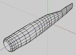
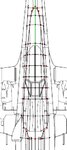
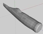
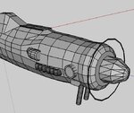
I started this thread as a way for everyone interested to monitor a G3 aircraft development progress from start to finish. The goal is to have a single thread which shows all of the steps involved with creating a new plane for G3. Maybe some newbies will find this useful, as enough of them have asked about it.

With this goal in mind, I would ask everyone to please refrain from making general comments on this thread (i.e. nice job, looking cool, I can't wait, or your art-work blows). If something is not clear and you have a question about it, please PM me and I will either edit my post to clarify it or just answer your question.

On the other hand; if any other developers have comments or recommendations that they would like to add, such as another way to do something, please feel free. These are the steps that I usually use and are not the only (nor may they be the best) way to do a lot of things. They are just the ones I'm comfortable with.

Edit: I recently received a request to expand the modeling portion of this tutorial to more of a step-by-step process, to aid those not comfortable with the modeling process itself. This new tutorial is too big to post, so if you send me a PM with an email address I'll send it to you. - Doug

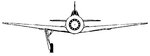
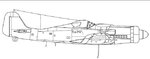
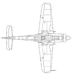
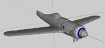
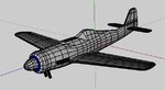
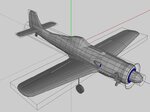
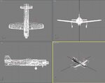
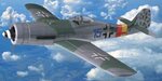
Here is the final objective, a replica of Top Flight's Gold Edition Focke-Wulf 190 D9:
 

Attachments

  • topa0150b.jpg
    topa0150b.jpg
    8.7 KB · Views: 305
Last edited:
Getting started:

The first step is to setup the basic dimensions of the aircraft. Do this by creating a Bounding Box to match the dimensions of your model.

Then take your 3-views and scale them to fit the bounding box and align them with each other.

Note: The program I'm using for most of my 3D work, at this point, is Wings 3D. It's simple, straight forward, and doesn't give me the headache 3DS Max does. 3DS Max can do everything Wings can and much more, but it's more program than I need right now. I will need to use 3DS Max for the final aircraft preparation later.

In case anyone would like to try this on themselves, here are the 3-views that this plane was modeled from.
 

Attachments

  • Image1.jpg
    Image1.jpg
    140.3 KB · Views: 432
  • Front 1.jpg
    Front 1.jpg
    20.4 KB · Views: 236
  • Side 2.jpg
    Side 2.jpg
    25.4 KB · Views: 215
  • Top 2.jpg
    Top 2.jpg
    36.3 KB · Views: 192
  • wing.jpg
    wing.jpg
    21.5 KB · Views: 173
Last edited:
Fuselage

Everything in a 3D modeler pretty much starts with primitive shapes (cube, cylinder, cone, etc.), and you pick the shape that is closest to what you're going to model.

Since the FW 190's fuselage is fairly round and long, that screams CYLINDER. So using a cylinder as a starting block, orientate and scale it to match the thickest round part of the fuselage in your 3-views.

Looking first from the top, segment the cylinder everywhere the fuselage changes shape. Then switch to a side view and do the same, also adjusting any of the segments placed while looking from the top as needed.
 

Attachments

  • Image2.jpg
    Image2.jpg
    44.8 KB · Views: 185
  • Image3.jpg
    Image3.jpg
    40.4 KB · Views: 165
  • Image4.jpg
    Image4.jpg
    36.5 KB · Views: 143
  • Image5.jpg
    Image5.jpg
    52.7 KB · Views: 158
Start shaping the cylinder to match the fuselage shape. Working from the top view, scale each segment to match the top view. Don't worry about how it looks from the side at this point, because as you can see you'll get a tube of varying diameters that doesn't match at all.
 

Attachments

  • Image6.jpg
    Image6.jpg
    38.7 KB · Views: 178
  • Image7.jpg
    Image7.jpg
    63.7 KB · Views: 191
Switching to the side view you can see that more segments will be needed to handle the shape of the canopy, so add some more.

Now start adjusting each segment again. Since you set the width in the last step, just adjust the height and vertical placement of each segment. Ignore the canopy for the moment and shape the fuselage as if it wasn't there.

When you are done with this step, you'll have the basic shape of your fuselage. With the 3-views turned off, you can get a better view of the whole shape. Look it over and go back and adjust any areas that do not smoothly flow from one to the next.

I haven't done that yet and you can see the area just before where the canopy starts bulges a bit and needs a little tweaking.
 

Attachments

  • Image8.jpg
    Image8.jpg
    38.8 KB · Views: 155
Start shaping the canopy area. Add nodes as necessary to get the shape required.
 

Attachments

  • Image9.jpg
    Image9.jpg
    33.4 KB · Views: 134
  • Image10.jpg
    Image10.jpg
    40.1 KB · Views: 181
After finishing the canopy area move on to adding some details to the fuselage. The details here are an airscoop, exhaust pipes, machine guns, and R/C engine & spinner.

The outline for the prop is called ~CS_ENGINE1 in Real Flight and it is not shown. It just used to tell the program where to spawn the propeller.

Since most 3D work is repetitive (i.e. take a crude shape and stretch & mash it into the shape you need), I'm not going to outline the steps to make each part. To keep this tread a resonable length, I'll just do that in key examples or where something interesting comes up.
 

Attachments

  • Image11.jpg
    Image11.jpg
    68.9 KB · Views: 158
The canopy and fuselage were shaped as one part so that the edges would match exactly, but now it is time to seperate them into two. Selecting the boundry lines between the two parts, cut them apart and move the canopy up out of the way. Then extrude the interior down so that you can later add details to the interior of the cockpit.

Define the bottom surface of the canopy as a "hole", so that it has no real surface and move the canopy back into place.

Note: The control surfaces of the wings will be seperated the same way as the canopy/fuselage. The entire wing structure will be made as one part and then the control surfaces will be cut out of it.
 

Attachments

  • Image12.jpg
    Image12.jpg
    35.5 KB · Views: 103
  • Image13.jpg
    Image13.jpg
    22.9 KB · Views: 96
  • Image14.jpg
    Image14.jpg
    37.2 KB · Views: 106
Main Wings

Wings can be a little complicated to model, but they are not hard. Since this is based off of a kit, look at the ribs in the plans. They may be different sizes, but if they all have the same shape it makes things easier.

As with nearly everything that is symetric on an aircraft (i.e. a left and a right wing), just model one side and then mirror it to get the other side.

Copy an image from the plans for a center rib. Align and scale the image with the side image of your 3-View. Hide everything but the rib image. Starting with a cube, flatten it down to 1/4" or so and stretch it out to the length of the rib. Add segments to the top and bottom to start shaping the contures. You'll need several close together to do the leading edge.

This gives you a fairly thin wing section at the center of the aircraft.
 

Attachments

  • Image15.jpg
    Image15.jpg
    24 KB · Views: 123
  • Image16.jpg
    Image16.jpg
    37.3 KB · Views: 119
  • Image17.jpg
    Image17.jpg
    21.9 KB · Views: 111
  • Image18.jpg
    Image18.jpg
    41.1 KB · Views: 120
  • Image19.jpg
    Image19.jpg
    25.8 KB · Views: 124
Move the outer face of the wing section out to the first place the leading or trailing edge makes a bend. Scale this face down to the correct size for this location on the wing and move it forward/backward as needed.

From this point extrude the face to the next bend and adjust it the same way. Continue out to the wing tip so that you get a nice wing structure.
 

Attachments

  • Image20.jpg
    Image20.jpg
    65.3 KB · Views: 143
Create a set of nodes that line up with the split between the flap & aileron and cut the wing in two at that point. Do the same for the other end of the flap.

Hiding everything except the part you are working on add nodes & lines for where the flap needs to be cut from the wing section.

Cut off the flap, delete any unneeded lines & nodes, and bevel the hinge line.

Use the same process to create an aileron. Then rejoin the wing sections (not the control surfaces) into one object.
 

Attachments

  • Image21.jpg
    Image21.jpg
    12.9 KB · Views: 92
  • Image22.jpg
    Image22.jpg
    49.1 KB · Views: 94
  • Image23.jpg
    Image23.jpg
    27.9 KB · Views: 90
  • Image24.jpg
    Image24.jpg
    24.7 KB · Views: 90
  • Image25.jpg
    Image25.jpg
    10 KB · Views: 104
Last edited:
Rejoining the wing sections completes one wing.

Switch to the front view and set the dihedral and vertical placement of the wing.

Adjust the center face to be vertically aligned and centered on the X axis. Use this face as a mirror point to create the other wing.
 

Attachments

  • Image26.jpg
    Image26.jpg
    45 KB · Views: 94
  • Image27.jpg
    Image27.jpg
    17.5 KB · Views: 90
  • Image28.jpg
    Image28.jpg
    17.6 KB · Views: 101
Last edited:
This is what we have to this point.

Here I'm going to take a break from the step-by-step and do the tail feathers. They are done by the same process as the wings.
 

Attachments

  • Image29.jpg
    Image29.jpg
    38.5 KB · Views: 166
Wrapping the tail feathers completes the major 3D construction of the aircraft. If you just wanted a hand-launched plane, you'd be nearly done with the modeling at this point

Now is a good time to make sure all of the parts that have just been created are named correctly. If they are not named correctly, Real Flight will not see them.
 

Attachments

  • Image30.jpg
    Image30.jpg
    37.6 KB · Views: 198
  • Image31.jpg
    Image31.jpg
    30.9 KB · Views: 322
Adding landing gear and collision meshes completes the 3D model. This is now ready to export to 3DS Max for final processing.
 

Attachments

  • Image32.jpg
    Image32.jpg
    68.4 KB · Views: 175
Here's the plane imported into 3DS Max. There are three things that have to be done to it in Max before it can be exported to Real Flight.

1) All aircraft parts need to connected in a hierarchy starting with the fuselage. In 3DS Max this is called linking.

2) All moveable parts need to have pivot points defined. These establish not only where the object pivots from but the direction it rotates.

3) And saving the best for last, a texture map needs to be created to color the plane.
 

Attachments

  • Image33.jpg
    Image33.jpg
    93.2 KB · Views: 211
Max Part 1 - Linking

Linking the hierarchy is pretty straight forward. Just as your fingers are connected to your hand, your hand is connected to your arm, and so on...

You do the same for every part you modeled. Here's what the linkages will look like:
 

Attachments

  • Image34.jpg
    Image34.jpg
    45.1 KB · Views: 329
Max Part 2 - Pivots

Setting pivot points is also pretty easy. Each moving part gets one (don't forget the collision meshes for the wheels).

In Max the axis which translates to the rotation axis in Real Flight is usually X (the red one). The exceptions are the engine & spinner, which for some reason use Y (the green one).

Be sure to align the axis with the hinge line (note this on the flaps & ailerons, which due to a tapered wing are off-axis). Also watch the alignment of the rudder since its axis is vertical. (See post #61 for a more detailed explanation - DHK)

This picture shows all of the pivot points for the moving parts.
 

Attachments

  • Image35.jpg
    Image35.jpg
    99.7 KB · Views: 340
Last edited:
Back
Top