Focke-Wulf 190 D9 development thread

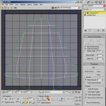
Max Part 3 - Texture Mapping

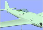
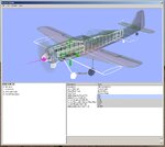
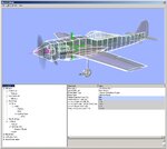
Add a blank TGA file as a diffuse color map to a Max material and assign that material to all parts, and this plane is at a point where it can be imported into Real Flight, but it doesn't look very good (and it won't fly, yet). So the next step is to texture map it.

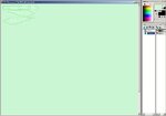
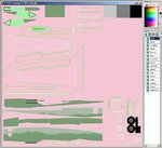
You'll need a good paint program that supports multiple layers (in its native format) and can save the picture as a TGA file with an Alpha channel. I use Paint Shop Pro, but there are many that can do it.

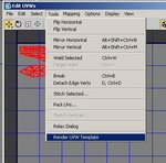
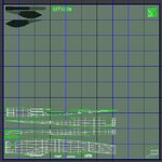
Texture mapping is a lengthly, tedious process that will take nearly as long as the entire rest of the project (if you do it right that is).
 

Attachments

  • Image36.jpg
    Image36.jpg
    75.1 KB · Views: 203
Last edited:
You have to texture each part one at a time. I always start with the canopy and then do any other transparent parts.

Select the canopy and add an Unwrap UVW modifier. Setup the Unwrap UVW options as shown in the first picture (including having your now blank TGA file displayed as the map. Select the canopy and apply a "flatten mapping" to it (the default options here will work fine). Select all of the pieces, scale them down, and move them to one corner of your TGA map.

Then as shown in the second picture "render the UVW template" and save it as a temporary bitmap.
 

Attachments

  • Image37.jpg
    Image37.jpg
    133.6 KB · Views: 160
  • Image38.jpg
    Image38.jpg
    38.6 KB · Views: 150
Note that in another paint program the steps used here may be different from these which are for Paint Shop Pro. Since there are so many paint programs that can be used, I'm not going to paste in a lot of pictures. Instead I'll list out the steps I take so that they can be applied to another program as needed.

The goal is to get the outline of the canopy parts on a transparent layer.

1) Open the UVW teplate you rendered from Max. Set the palatte transparency to the background color (normally black), and copy the image to the clipboard.

2) Open/create a blank picture in the native format. Set the background to a light color that will not be used on the aircraft and set that as the palatte transparent color (I used a light lime green).

3) Paste the UVW template as a new layer in your drawing.

4) Create a new layer named "Canopy" and make sure it's above the UVW layer.

5) Copy the region of the UVW layer that has the canopy parts in it.

6) Switch to the Canopy layer and paste what you copied as a transparent selection. Since you can see through the layer, it is easy to set the selection down directly over where it came from (but on another layer).

7) Delete the UVW layer (with its black background) and you've achieved the goal.
 

Attachments

  • Image39.jpg
    Image39.jpg
    67 KB · Views: 121
I find that the transparent sections are the most tetious. Frequently working on a few pixels at a time, on either the color or alpha channel.

Then switching back & forth between Paint Shop, Max, and Real Flight. While the preview in Max is pretty good for most work, if you need pixel by pixel alignment I always find it's best to look at how it will be rendered in the final program.
 

Attachments

  • Image40.jpg
    Image40.jpg
    19.5 KB · Views: 81
Im just here to say thanks for doing this model.

I just hope you dont reproduce the crappy cowl that was on the TF plane.
 
With the canopy and alpha map done, it's time to start added the other major components. Try to visualize how you want the full texture map to be laid out, as you only have one and everything has to fit on it.

Add and flatten parts one at a time and as you update the TGA file you can see it in the UVW editor so it is easy to place the next part.

A couple of points to remember:

1) Parts that are solid color (like most spinners) do not need to be flattened. Have a small area of the color on the texture map and scale the UVW way down to fit in it.

2) Parts may overlap on the texture map. If both wings are the same (or mirror images of each other), you only have to do the texture for one and use it on both.

3) There may be some parts that you will not want to flatten (pilot figures, for example. Just try flattening one and then figure which piece is which and get your painting of it to look good). These can often be textured using a front/back or top/bottom map, which will flatten out the sides a bit but will keep most of the part intact. 3D games, like "Half Life" use this type of mapping.


In the second picture, I've added and flattened the fuselage. Just to the right of the canopy are a bunch of panels from the inside of the cockpit. These are going to be a solid color, so they are just stacked on top of each other. In the top right corner are all of the pieces that make up the exhaust pipes. They are going to be solid black and so they didn't really need to be flattened, but they got smashed with the fuselage. To the right of the main fuselage parts are the pieces that make up the instrument panel. I may do something with them later, so I'm keeping them separate.

When you go to the paint program with each part, put them on a separate layer of your master texture. This allows you to move and scale the parts separately, if you need to adjust their placement later.

Also add decals and markings on thier own layer for the same reason.

The steps are the same for each new part, so I'm going to go off and finish mapping the parts. I'll post several in progress pictures when I'm done.
 

Attachments

  • Image41.jpg
    Image41.jpg
    20.9 KB · Views: 104
  • Image42.jpg
    Image42.jpg
    63.9 KB · Views: 123
Last edited:
Why not simply use a seperate material for your transparent parts and turn down the opacity in the material editor window,thats the way i do it.Makes it loads easier and quicker.
 
inky00 said:
Why not simply use a seperate material for your transparent parts and turn down the opacity in the material editor window,thats the way i do it.Makes it loads easier and quicker.

Actually the canopy is a seperate material in MAX. The canopy is defined as ~CANOPY (i.e. show both sides & transparent) and most of the rest of the plane is ~SBS (show both sides). I have the trasparancy set by alpha because of the bars on the canopy of this plane, you do not want these to be transparent.
 
All of the other parts have been added to the UVW map and placed on a seperate layer in the master texture file.

The texture still needs to be painted, but that does not add much to the tutorial. So let's import this into Real Flight for the last step of the process.
 

Attachments

  • Image43.jpg
    Image43.jpg
    117.8 KB · Views: 159
Last edited:
In Real Flight open the new plane up in the editor and you'll see that nothing matches up.

Starting with the fuselage make the Real Flight physics model match up with the 3D one.

Move from one part to the next until you get the whole plane done.
 

Attachments

  • Image44.jpg
    Image44.jpg
    110.9 KB · Views: 193
  • Image45.jpg
    Image45.jpg
    122.4 KB · Views: 192
This pretty much ends the tutorial, which was to start with nothing but a couple of drawings and get something resembling a plane into Real Flight.

There is still a lot of work to be done to this plane before it is ready for me to post to the swap pages, but all of the steps in the development process have been covered.

What's left:

1) Finish the texture map.
2) Take a very close look at how everything renders and go back and tweak both the 3D model (I already modified the flaps) and texture map as needed.
3) Add a few gingerbread features like an instrument panel, pilot, and maybe retracts.
4) Correct the default weights of all components in Real Flight.
5) Correctly define the airfoils used for the wings & tail surfaces (we have the basic shapes, but not the cross-sections).
6) Trim and balance the aircraft for proper flight performance.

At this point I'm going to get off of my soap-box and open this thread up for comments, questions, and general discussion.
 
Last edited:
I've spent a lot of time on this plane/tutorial this weekend, but Monday it's back to work.

I'd guess I still have about twenty hours worth of work, so it really depends on how much time I can spend on it over the next few days.

At the moment it just has fixed gear and no doors. Who knows, I may refine that later. But I would expect the initial release to have the fixed gear.
 
Not following the order of things to do that was posted above, I completed 4, 5, & 6 first.

She still looks a bit scanky, but the physics model has been tweaked to balance and trim the Focke-Wulf. She now flies pretty much like most WWII warbirds of the same size.

This is not ready for the swap pages, but if anyone who has been following this thread would like to try it out - here's a preview.
 

Attachments

  • Image45.jpg
    Image45.jpg
    115.7 KB · Views: 254
Last edited:
every thing looks great so far dhk79, I love the teach thread to. One quick question, does 3ds max have to be used for the moveable parts or can wings 3d work. Once again huge thanks. :D
 
wulf 190 said:
does 3ds max have to be used for the moveable parts or can wings 3d work. Once again huge thanks. :D

3DS Max is needed for the three processes listed in post #18 of this thread. Wings 3D, while a great 3D modeler, can not handle these functions.

I'm pretty much done with this bird other than a final quality check and then putting it through its paces for a bit, to make sure it has no unexpected bad habbits.

The full scale FW 190 used a NACA 23015.3 to 23009 airfoil as its main wing. This gave the FW 190 a very abrupt stall. Top Flight did not use this same wing in its kit, but chose one with a milder stall. Since you wanted a replica of the TF kit, I matched the kit's wing rather than going for full scale type performance.
 

Attachments

  • Image46.jpg
    Image46.jpg
    140.2 KB · Views: 169
Last edited:
I like the plane being a top flight fan, did you not include retracts? it flys great with those wheels hanging down doesn't quite look like a tru warbird any plans on including them?
 
Back
Top