Help! RealFlight Evolution Aircraft Design for newbs.

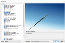
So I found out there's an add-on to view pivot points. Using the "Precision Drawing Tool" PDT add-on ... I might have thought one would not have to add this on but anyway... one accesses this from the Edit->Preferences menu

View attachment 138904

To open up this tab alongside the right of the viewport

View attachment 138905

Seems like nothing in Blender is easy nor intuitive.

I may be able to view all pivot points with their vectors soon

I have never used that.

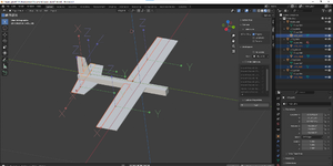
the size difference in the model's arrows is likely because I model in Wing3d in Inches then when it goes to blender it converts it to metric. so a 60 ich wingspan endup like 60 meters. then in the export I set the units to FBX unit scale which fixes it.
 
Ok, so one fix may be if I just scale up my model. I think my current model is maybe 2m in length. If I scale it up giant sized, I can always scale it down?

I'll try that.

Having trouble trying to affect a rotation at any pivot point currently as I can't see what result I'm getting. Thanks for the tips.
 
Scaled it up a factor of roughly ten, lol.

1712774570241.png

I must be doing something wrong. The fuse is nearly 20 m long.

Surely I've messed up somehow.

Also, I seem to be only seeing the orientation of the pivot points correctly in my view port if I select them all and checking the "apply transform to origin only" box. Still not sure how to see the orientation of an individual pivot point on its own. I don't think that PDT tool I tried earlier helped at all.

Thanks for all the help thus far! Really appreciate your help - can imagine this is basic stuff, but not really exactly sure where I can learn just all I need to know.
 
Scaled it up a factor of roughly ten, lol.

View attachment 138906

I must be doing something wrong. The fuse is nearly 20 m long.

Surely I've messed up somehow.

Also, I seem to be only seeing the orientation of the pivot points correctly in my view port if I select them all and checking the "apply transform to origin only" box. Still not sure how to see the orientation of an individual pivot point on its own. I don't think that PDT tool I tried earlier helped at all.

Thanks for all the help thus far! Really appreciate your help - can imagine this is basic stuff, but not really exactly sure where I can learn just all I need to know.

I am not sure why the arrows are different size it might be a setting.

here is the rotate.

2024-04-10 02_42_49-Settings.png

if it is throughly hosed. you can try clearing the rotation


2024-04-10 02_44_29-Blender_ [D__Robert_Documents_Wings 3d_B-42 43 mix jet master_B-43 v3.blend].png
 
Thanks for the tip about clearing botched rots. I needed that one.

I think the biggest problem I'm having right now is trying to tell Blender to do what I'd like per the KE docs and the 3DS max tutorials. The program seems to be just so idiosyncratic (in my opinion) that if one doesn't know how to do something, it's not immediately obvious how one might find out. After a lot of trial and error, I found that by

1. fixing the transformations to origins only per the checkbox
2. Using the size tool,

I could resize the arrows. Like so

1712860907103.png

I still don't know how they got so ginormous to begin with.

Also, I probably need to fatten those arrow axes up, I can barely see them.

I guess since I can now rot the pivots and righten them up to what the docs demand, the next step is UV mapping. That sounds like it's going to be real fun. Any good quick guides on how to do this?
 
Interestingly, a few gotcha's I discovered with blender...

Even with the transform limited to origin checked as thus...

1712861281275.png

If you use the item dialog box it will still scale the object

1712861545497.png

I circled the wrong z - btw, I meant the scale not the rotation. correction


Oh well, maybe that's considered a 'scale' operation and not considered a 'transform'? I dunno

And yeah, I guess I'm not too amused about the way Blender is so... cryptic this way but it appears it's currently the only realistic tool I have moving forwards for now, anyway.
 
I can't even understand why this is happening...

I'm trying to clear the rotation on that pivot point of the wing - not that it's necessary, it's not a moving surface, but just to tidy up those arrows.

1712863830531.png


Do that and I get this bizarre transform

1712863923335.png


I mean, I don't even understand why it would flip the aileron when it wasn't even selected. And transform is supposed to be limited to the origin point as the box is checked?

Bizarre.

I'd like to believe it's something I just don't understand but maybe it's just a bug?
 
Great progress folks!

I managed to texture map something to that silly little plank I drew up following this video.


Resulting model looks like (sans light and camera object)

1712951054329.png

I just randomly grabbed a TGA texture off the web.

However, when I imported it, I ended up with this strange looking phenomenon in RF Evolution. There's this weird flat polyhedron I've no idea where it came from, take a look

1712950737931.png

1712950930173.png

I can't seem to find any object that corresponds with that extremely slender and disproportionate object.

Plus side, I managed to get RF Evo to import something, minus side it's still not good.

Any ideas what I did wrong? Cheers

At first, I thought it might have been the light and camera object acting as points for an occult polyhedron but I removed them and that poly is still there.
 

Attachments

  • 1712950586799.png
    1712950586799.png
    835.4 KB · Views: 4
  • 1712950818598.png
    1712950818598.png
    240.7 KB · Views: 3
Somehow I think my pivoting is messed up.

Here's the model with full left aileron

1712952006851.png

full right aileron

1712952047550.png

What's really odd is in the prior post I have, it looks like the pivot points look correct.

Any ideas, guys? Thanks!
 
No landing gear so I handlaunched it
1712952803902.png

Seems to fly but I've no idea where that other object came from! I suppose it flies because I chose a known prior model to inherit its physics from but clearly there's something wrong with this actual model!
 
@spykez I would be happy to look over the model if you want to post the ea here.

it looks like it does not have smoothing groups. or an edge split modifier has not been applied. I am not sure what the large polyherda is or where it came from.

I would be happy to help you with learning to model I have a discord server where I help people learn anyone who want to learn can join.

Thanks so much!

I suspect when I was laying down all the initial meshes I might have just transformed them so much, or misapplied some blender tool so that something went awry and I probably cannot trace it. I mean, I suspect there's probably a lot of mistakes and undo's in the blender file for this.

Chalk it down to total lack of experience and knowledge here!

I wonder if I redo the model from scratch will I have the same side effects.

Discord is another thing I need to look at - I'll need to go download it. I'm quite social media inept, apart from forums. I'll catch up with you either here or on your discord early next week, say Monday? - going away for the weekend!
 

Attachments

  • basic_plank7_EA.RFX
    662.4 KB · Views: 2
If you look at the model in the vehicle editor, select "Visuals" and click on the large plank item the editor highlights it as the Left Main Elevator. (~CS_LME).
 
the huge shape is the ~CS_LME and the ~CS_RME is also very deformed.
2024-04-12 18_30_55-Aircraft Editor - basic_plank7.png

also it looks like all the control surface pivots are 90 degrees off

these are the correct orientaions for the pivots

1712960880206.png

these are not which is what is on the model.
1712960961194.png
 
Thanks so much!

I suspect when I was laying down all the initial meshes I might have just transformed them so much, or misapplied some blender tool so that something went awry and I probably cannot trace it. I mean, I suspect there's probably a lot of mistakes and undo's in the blender file for this.

Chalk it down to total lack of experience and knowledge here!

I wonder if I redo the model from scratch will I have the same side effects.

Discord is another thing I need to look at - I'll need to go download it. I'm quite social media inept, apart from forums. I'll catch up with you either here or on your discord early next week, say Monday? - going away for the weekend!
@spykez Congratulations on your first import of a model into RF, it certainly is a great feeling to see that first model fly. Keep them models coming.
 
the huge shape is the ~CS_LME and the ~CS_RME is also very deformed.
View attachment 138978

also it looks like all the control surface pivots are 90 degrees off

these are the correct orientaions for the pivots

View attachment 138976

these are not which is what is on the model.
View attachment 138977

Thanks guys all of you! Away from the PC this weekend but I'm almost sure the pivots on the model I exported were correct - but I can't check them now. The white rendered picture you linked was the most recent model (with the styrofoam texture). The second wireframe image you link is from an earlier version.

Unless the pivots did not transfer. Hmm... Well, they very clearly didn't with the warped control surfaces.. They look fine in Blender that's the issue.

I'll have a look when I get back, maybe there's just so many mistakes and undos in the original blender file there may be a hidden command or pivot that's just not evident that is persisting and messing things up.

I probably need practice getting to know Blender so there's no harm creating another basic model. I think that's what I may do.
 
It's great seeing you interested in 3d modeling and learning how to do it. I've been following your build thread since the beginning. You have a great start so keep going the prize is in sight and waiting for you. It reminds me of all the struggles I went through learning how to do it. Hang in there.
 
Thanks for your words of encouragement! They mean a lot to me, all of you!

When I'm back home Monday I'll just redo the basic model and see if I can get a different result!

I think I maybe understand what the KE beginner doc wants but biggest trouble I'm having is telling Blender to do it, hahaha

Have good weekend all!
 
Hey just found yalls thread. Been having my own problems. The model I have is made formatted correctly and with tga file connected. However, I keep getting an error about too many vertices, however, I have downgraded the model on 3D Max quite a lot and it still gives me the message.
I am going from Solidworks to 3D Max, then to blender; so I assume I'm overcomplicating the process somehow, I am just stuck.

there is a single object limit 65,535 and the aircraft limit it 135,000 triangles. 3dsmax has all the capacities to make models for rf so you can skip blender.
 
Back
Top