You are using an out of date browser. It may not display this or other websites correctly.
You should upgrade or use an alternative browser.
You should upgrade or use an alternative browser.
Turbine Toucan Build
- Thread starter abaser
- Start date
abaser
Well-known member
On the way back to work, I had an idea. Could it be that my inside faces of the fuse are too close to the outside faces and they are trying to overlap or share the same space? To me, that would explain the backwards lettering, and the reason they appear that they are not selected.
Boof69
Well-known member
Can you make the inside pieces separate geometry and map them individually? It would seem that if wings uses projection mapping that two overlapping face would give problems. I don't know about wings but in max I would detach those inner pieces from the rest of the fuse, map then them reattach them when mapping was complete. I could be way of base or maybe this is something you've already tried, but it would seem that it's the most likely solution.
abaser
Well-known member
The inside of the fuse was intruded in. I thought (might be thinking wrong) that I scaled the inside down a bit to avoid this situation. But when I tried this morning, it distorted the outside of the fuse as well at the breakoff point. Im hoping there is a fairly simple fix, maybe extrudeing the inside a bit, or extracting even. Thats the plan for when I get home anyway.
One thing for sure, If this idea works, I can say I did it and probably wont try it again for a while. Its a lot more work than I bargained for, thats for sure.
One thing for sure, If this idea works, I can say I did it and probably wont try it again for a while. Its a lot more work than I bargained for, thats for sure.
abaser
Well-known member
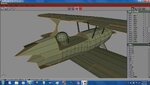
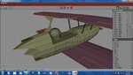
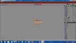
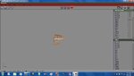
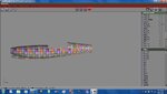
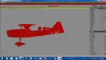
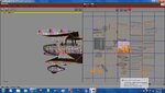
Here's where things get strange to me. I have four pieces of the fuse. 2 frame parts and 2 fuse parts. When I combine ONLY those four parts, things seem ok. BUT when I combine the rest of the parts, thats when the faces show through. I have figured out that it is the inside faces showing through, and if you scroll around, looking at the fuse at different angles, they appear and dissappear in different places. I am in the process of trying to figure out the best way to eliminate that problem, but what Im wondering is, why does the combining of the fuse parts to parts other than the fuse make these faces show?
Note: the camera angle is the same in each screeny, so that is not why the faces become visible as mentioned earlier.
Note: the camera angle is the same in each screeny, so that is not why the faces become visible as mentioned earlier.
Attachments
jeffpn
Well-known member
It won't show through in RF anyway. My AG14 was a victim of Z-fighting, but I left it alone. In Wings, you can see one side poking through the other. In RF, the problem does not show. If you can't (or don't want to) adjust the size, let it be a learning experience. Look at pic#24 of this tute. https://forums.realflight.com/showpost.php?p=203323&postcount=59 I ended up trianguating all the faces the same direction to eliminate the z-fighting.
flexible
New member
Rethink what the CS will look like. Parts that are going to have detail, need to be larger so the detail will show. parts that are one color can be any size, and can be put in a pile, moved to some unused spot, sized down, and later just paint that area with the solid color. Solved.
abaser
Well-known member
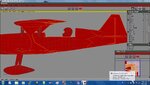
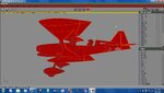
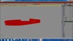
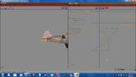
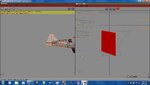
Well, if I havnt mentioned it before, Ill say it now.........I HATE MAPPING  . It looks like Im going to put this on a SLIGHT hold for a bit while I go back through some mapping tuts. While moving things around, Ive run into several parts like this. They are attached to a square oblect that highlights with the shape of another that will not highlight Im lost as to what is causing it and I feel I need to redo everything just to make sure things are right.
. It looks like Im going to put this on a SLIGHT hold for a bit while I go back through some mapping tuts. While moving things around, Ive run into several parts like this. They are attached to a square oblect that highlights with the shape of another that will not highlight Im lost as to what is causing it and I feel I need to redo everything just to make sure things are right.Attachments
Maybe if you switch to select line (or vert) you could select one of the lines/verts then, without deselecting, go to object (or whatever it was) and find the whole part on the mapping window and on thd plane. And maybe delete it/remap it. Or you could probably just move it and fix it, depending what happens to the map texture on the plane when you find what it is. Show pics of what you find.
Last edited:
flexible
New member
Hold on, If you don't reognize it, it is most likley something you added inadvertly. While in object mode, Delete, and it is gone.
It looks like it might be an image, showing up.
If you put all the parts you want to Map, in a folder named (MAP PARTS). Check the list.
When you go to Map, first lock all parts. Then open the MAP PARTS folder, Combine those parts. Next select one Face on the first part you want to Map. Then hold the F key down, which selects all the Faces on that part, then click the uvw tool.