Madratter
New member
Unquestionably separating it does give more control. I would be interested in how exactly Knife Edge breaks down the fuselage for modeling the physics. This isn't the first time I have wondered about it.
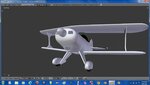
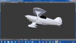
What is so interesting about the fuselage in particular, is that unlike the other pieces like the wings, the fuselage is represented exactly in the physics model visual. I'm curious to what extent that is eye candy and to what extent it actually matters in terms of the physics modeling they do.
There are certainly nuances of wings that they are missing because they don't do the exact modeled profile. The wing on my Yak is an example of that.
 I know Im less than double the count because there are several tri's already from adding the ribs.[/QUOTE]