uncle twist
Well-known member
Beautiful job on the wheels Andy....!!!! ")
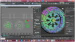
If you made seam selections that trace the spokes and only one seam on the thickness the entire loop of polys that are the thickness will map as a single piece. I noticed all of the edges are green seams so the polys would break out individually, and need to be stitched.So here’s a quick shot of the wheel mapping. You can see the edges I marked as seams highlighted in green before doing the peel mapping. After marking those, one click and this is the result. The ONLY modification I made to the end result was straightening the tread edges as Boof69 points out in his video.
No stitching required this way. Each poly defining the thickness is cut on 3 sides. The edge that isn’t marked as a seam becomes like a hinge and the face just rotates and lays flat. I’ll post a pic of the uv editor later to show what I mean.If you made seam selections that trace the spokes and only one seam on the thickness the entire loop of polys that are the thickness will map as a single piece. I noticed all of the edges are green seams so the polys would break out individually, and need to be stitched.
Are you planning to paint the inside (depth of the wheel) a different shade of the same color to highlight it? If not why can't you select the whole wheel and map it using the x-axis and do the same thing to the back of the wheel then overlay them on the cs map. I've done that and they paint okay so I'm asking to learn something. Now with a texture I'm sure there would be stretching but for a solid color it works for me. I've also done the front and back of the wheel and overlaid them then selected the inner polys of the wheel and mapped those separately so I could paint it a slightly darker shade of the same color to highlight that part of the wheel. I'm definitely waiting to see what your uv map looks like.No stitching required this way. Each poly defining the thickness is cut on 3 sides. The edge that isn’t marked as a seam becomes like a hinge and the face just rotates and lays flat. I’ll post a pic of the uv editor later to show what I mean.
Okay, got it. I was thinking maybe you were planning to put some sort of bitmap on it like I've seen on a few wheels out there. Sort of like those props with bitmaps on them.I did this as an experiment really. It’s not so much for the wheels as most of the wheel will be covered by the wheel pants, but for future reference for items such as the holes in the bottom of my fuselage.
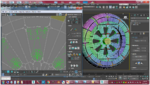
Here's what the wheel UVs look like. Here you can see how the depth faces folded into place. If this was a more noticeable part, I would definitely fix the overlapping faces, but in this case I'll probably just leave them as is.Are you planning to paint the inside (depth of the wheel) a different shade of the same color to highlight it? If not why can't you select the whole wheel and map it using the x-axis and do the same thing to the back of the wheel then overlay them on the cs map. I've done that and they paint okay so I'm asking to learn something. Now with a texture I'm sure there would be stretching but for a solid color it works for me. I've also done the front and back of the wheel and overlaid them then selected the inner polys of the wheel and mapped those separately so I could paint it a slightly darker shade of the same color to highlight that part of the wheel. I'm definitely waiting to see what your uv map looks like.
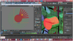
Ok, what you see on the center hub is basically what you’re seeing with the depth faces of the wheel. The “rectangles” are actually the faces making up the sides of the hub. They were cut on 3 sides, but the 4th edge is still attached to the center portion of the hub. When you peel map that, those faces will basically “hinge” on the edge that’s still attached to the center. For example, if you have a cardboard box, cut that box along the corners so that you can spread it out and make it flat, but still one piece. That’s all I’m doing here except with a cylinder.Very interesting, thanks. Why does the center hub mapping look like it has thin rectangles sticking out all the way around the hub but they're not connected? And the detail in the wheel mapping for the front and back look different. Or at least I think the front of the wheel is on the left side and the back of the wheel is in the middle. Sorry about the 20 questions but I'm really curious about what I see. And thanks for explaining what you're doing with it.
Okay cool that makes total sense, the peeling is what I saw but didn't realize what I was looking at. Thanks for the explanation. I'm heading off the bed I'll checkout your new picture when I get up. Later.Ok, what you see on the center hub is basically what you’re seeing with the depth faces of the wheel. The “rectangles” are actually the faces making up the sides of the hub. They were cut on 3 sides, but the 4th edge is still attached to the center portion of the hub. When you peel map that, those faces will basically “hinge” on the edge that’s still attached to the center. For example, if you have a cardboard box, cut that box along the corners so that you can spread it out and make it flat, but still one piece. That’s all I’m doing here except with a cylinder.
As for the wheel halves looking different, one has the depth faces still attached to it while the other doesn’t. Give me a few and I’ll post a pic hopefully clearing things up.
I guess I just have this idea in my head and I have this need to make it work. In my mind, I like to know what everything on the map is. If I were to come across a map where someone mapped the thickness as strips, I'd more than likely go crazy trying to figure out what the hell they went to.So what is the reason you wouldn't map those spoke hole thickness polys as simple strips and stack them in one spot for instance? Just curious.
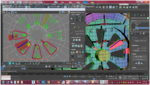
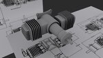
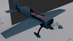
We’ll see where it goes. I’m going try and make it all but who knows.That DA is looking Fantastic Andy...!!!..Dare I ask, are going to model the engine with all/most of the detail/parts in the third pic...???...How far do you plan too go with it..??
Thanks.Looks incredible, nice work.
I figured you’d like it. ? I just hope I can make it all happen. I got a little stumped when it came to making the left cylinder meet up to the crankcase though. I’ll get it figured out, just got to look close at my reference pics.We’ll see where it goes. I’m going try and make it all but who knows.