abaser
Well-known member
Just keep a thick skin and you're in good shape.and ribbing to keep you going.
Just keep a thick skin and you're in good shape.and ribbing to keep you going.
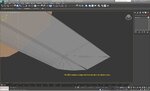
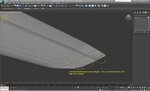
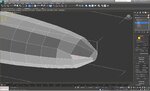
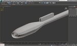
Lofting.
Wings made on all the models so far have been by extruding from the root airfoil and then shape as needed. The lofting technique is reported to also be useful, but have had no success with it so far. Would like to add to the list of earned techniques. Following Boof's tut, the shape is clearly outlined and shown, but there is no selection displayed for the last "get shape" step.
Am obviously missing a setting or sequence order.
In addition to myself, others may be having difficulty with this-- now or in the future.
Suggestions of things to check for?
Thanks
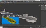
I see you have an overlay of the plans in 3ds Max; would you mind sharing a quick tip in how you did so?
Thanks
Curtis
Montana
I'd go with solid teal, it's a very popular color
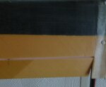
1. The eye dropper will pick up a single pixel's color. In a photo that may or may not be what you are looking for. Better bet is get RGB values of standard colors from Simmer's Paint Shop http://www.simmerspaintshop.com/page-colorindex.html1. The PS eye dropper should be able to make a good copy of the red, blue, and bright yellow, true?
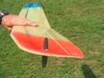
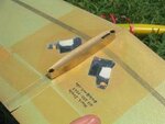
2. The wing pylon looks like it has a polished brass surface (unless that is a kevlar reflection). Suggestions to make a polished brass material?
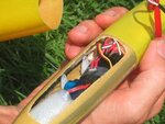
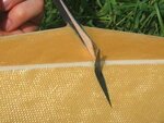
3. There are some good pictures of the kevlar. The eye dropper can get that color
as well, but how can the fabric pattern be copied?
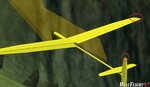
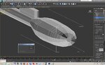
). There are a few odds & ends to finish off, but the VS & Rudder were not quite as I wanted them to look (to match the plans) and it took a few passes until that was correct.